Page 161 of 227

26 Dashboard trim panels-
removal and refitting
2
Warning: Later models are
equipped with airbags. To
prevent the accidental deploy-
ment of the airbag, which could
cause personal injury or damage to the
airbag system, DO NOT work in the vicinity
of the steering column or instrument panel.
The manufacturer recommends that, on
airbag equipped models, the following
procedure should be left to a dealer service
department or other repair workshop
because of the special tools and techniques
required to disable the airbag system.
Caution: If the stereo in your vehicle is
equipped with an anti-theft system, make
sure you have the correct activation code
before disconnecting the battery
Knee bolster
1Knee bolsters are located on the lower half
of the instrument panel on the driver and
passenger sides of the vehicle. The removal of
these covers will allow access to a variety of
electrical, heating and air conditioning
components.
2Detach the retaining screws along the
edges of the knee bolster (see illustration).
3Pull outward on the lower edge of the knee
bolster and detach it from the vehicle.
4Refitting is the reverse of removal.
Centre trim panel
5Carefully pull outward to detach the centre
trim panel from the instrument panel (see
illustration).
6Refitting is the reverse of removal.
Glove box
7Detach the passenger side knee bolster as
described in Steps 2 and 3.8Remove the glove box door hinge bolts
(see illustration).
9Open the glove box door, then detach it
from the vehicle.
10Detach the heater duct and the relay
mounting panel from the bottom of the glove
box.
11Detach the remaining screws securing the
upper edge of the glove box (see illustration).
12Disconnect the lamp from the glove box
and remove the assembly from the vehicle.
13Refitting is the reverse of removal.
27 Steering column cover-
removal and refitting
2
Warning: Later models are
equipped with airbags. To
prevent the accidental deploy-
ment of the airbag, which could cause
Bodywork and fittings 11•13
11
3261 Jaguar XJ6 26.2 Remove the retaining screws along the outer edge of the
knee bolster, then remove it from the vehicle
26.5 Grasp the centre trim panel with both hands, then unsnap
the retaining clips (arrowed) from the dashboard assembly
26.8 With the passenger side knee bolster removed, unscrew the
glove box door hinge bolts26.11 Remove the screws along the top edge (arrowed), pull the
glove box out and remove the lamp assembly
Page 162 of 227

personal injury or damage to the airbag
system, DO NOT work in the vicinity of the
steering column or instrument panel. The
manufacturer recommends that, on airbag
equipped models, the following procedure
should be left to a dealer service
department or other repair workshop
because of the special tools and techniques
required to disable the airbag system.
1Remove the steering wheel (Chapter 10)
2Remove the knob from the rheostat
(dimmer) for the instrument panel lights (see
illustration).
3Remove the lower steering column cover
screws (see illustration), then detach the
lower cover.
4Working through the lower cover opening,
remove the four screws securing the upper
half of the cover, then pull the cover forward
and out to remove it (see illustration).
5Refitting is the reverse of removal.
28 Cowl cover-
removal and refitting
2
1Remove the windscreen wiper arms (see
Chapter 12).2Remove the retaining screws located along
the top of the cowl cover (see illustration).
3Lift the cowl cover up slightly, then detach
the electrical connectors and the spray nozzle
hoses from the backside of the cowl cover.
4Detach the cowl cover from the vehicle.
5Refitting is the reverse of removal.
29 Seats- removal and refitting
2
Front seat
1Position the seat all the way forward or all
the way to the rear to access the front seat
retaining bolts.
2Detach any bolt trim covers and remove the
retaining bolts (see illustration).
3Tilt the seat upward to access the
underneath, then unplug any electrical
connectors and lift the seat from the vehicle.
4Refitting is the reverse of removal.
Rear seat
5Remove retaining screws at the lower edge
of the seat cushion (see illustration). Then lift
up on the front edge and remove the cushion
from the vehicle.
6Detach the retaining bolts at the lower edge
of the seat back.
7Lift up on the lower edge of the seat back to
release the clips securing the top. Then
remove it from the vehicle.
8Refitting is the reverse of removal.
11•14 Bodywork and fittings
27.4 Remove the four screws securing the
upper half of the steering column cover
28.2 Remove the screws (arrowed)
located along the top of the cowl cover29.2 Use a Torx bit to remove the front
seat retaining bolts (arrowed)
3261 Jaguar XJ6 27.2 Pull off the knob from the instrument panel light rheostat
27.3 Remove the lower steering column cover screws
29.5 Detach the screws (arrowed) along
the lower edge of the seat cove
Page 163 of 227

3261 Jaguar XJ6
12
Chapter 12
Body electrical system
1 General information
The electrical system is a 12-volt, negative
earth type. Power for the lights and all
electrical accessories is supplied by a
lead/acid-type battery which is charged by
the alternator.
This Chapter covers repair and service
procedures for the various electrical
components not associated with the engine.
Information on the battery, alternator,
distributor and starter motor will be found in
Chapter 5.
It should be noted that when portions of the
electrical system are serviced, the cable
should be disconnected from the negative
battery terminal to prevent electrical shorts
and/or fires.
2 Electrical fault finding-
general information
A typical electrical circuit consists of an
electrical component, any switches, relays,
motors, fuses, fusible links, in-line fuses or
circuit breakers related to that component
and the wiring and electrical connectors that
link the component to both the battery andthe chassis. To help you pinpoint an electrical
circuit problem, wiring diagrams are included
at the end of this Chapter.
Before tackling any troublesome electrical
circuit, first study the appropriate wiring
diagrams to get a complete understanding of
what makes up that individual circuit. Trouble
spots, for instance, can often be narrowed
down by noting if other components related to
the circuit are operating properly. If several
components or circuits fail at one time,
chances are the problem is in a fuse or earth
connection, because several circuits are often
routed through the same fuse and earth
connections.
Electrical problems usually stem from
simple causes, such as loose or corroded
connections, a blown fuse, a melted fusible
link or a bad relay. Visually inspect the
condition of all fuses, wires and connections
in a problem circuit before diagnosing it.
If testing instruments are going to be
utilised, use the diagrams to plan ahead of
time where you will make the necessary
connections in order to accurately pinpoint
the trouble spot.
The basic tools needed for electrical fault
finding include a circuit tester or voltmeter (a
12-volt bulb with a set of test leads can also
be used), a continuity tester, which includes a
bulb, battery and set of test leads, and a
jumper wire, preferably with a circuit breaker
incorporated, which can be used to bypasselectrical components. Before attempting to
locate a problem with test instruments,
use the wiring diagram(s) to decide where to
make the connections.
Voltage checks
Voltage checks should be performed if a
circuit is not functioning properly. Connect
one lead of a circuit tester to either the
negative battery terminal or a known good
earth. Connect the other lead to a electrical
connector in the circuit being tested,
preferably nearest to the battery or fuse. If the
bulb of the tester lights, voltage is present,
which means that the part of the circuit
between the electrical connector and the
battery is problem free. Continue checking the
rest of the circuit in the same fashion. When
you reach a point at which no voltage is
present, the problem lies between that point
and the last test point with voltage. Most of
the time the problem can be traced to a loose
connection. Note:Keep in mind that some
circuits receive voltage only when the ignition
key is in the Accessory or Run position.
Finding a short
One method of finding shorts in a circuit is
to remove the fuse and connect a test light or
voltmeter in its place. There should be no
voltage present in the circuit. Move the wiring
harness from side to side while watching the
test light. If the bulb goes on, there is a short Airbag system - general information . . . . . . . . . . . . . . . . . . . . . . . . . 28
Bulb renewal . . . . . . . . . . . . . . . . . . . . . . . . . . . . . . . . . . . . . . . . . . . 21
Central locking system - description and check . . . . . . . . . . . . . . . . 25
Circuit breakers - general information . . . . . . . . . . . . . . . . . . . . . . . . 5
Cruise control system - description and check . . . . . . . . . . . . . . . . . 23
Direction indicators/hazard flashers - general information . . . . . . . . 7
Electric aerial - removal and refitting . . . . . . . . . . . . . . . . . . . . . . . . . 14
Electric side view mirrors - description and check . . . . . . . . . . . . . . 26
Electric sunroof - description and check . . . . . . . . . . . . . . . . . . . . . . 27
Electric window system - description and check . . . . . . . . . . . . . . . 24
Electrical fault finding - general information . . . . . . . . . . . . . . . . . . . 2
Fuel, oil and temperature gauges - check . . . . . . . . . . . . . . . . . . . . . 11
Fuses - general information . . . . . . . . . . . . . . . . . . . . . . . . . . . . . . . . 3
General information . . . . . . . . . . . . . . . . . . . . . . . . . . . . . . . . . . . . . . 1
Headlight housing (1992 to 1994 models) - removal and refitting . . . 19Headlights - adjustment . . . . . . . . . . . . . . . . . . . . . . . . . . . . . . . . . . 18
Headlights - renewal . . . . . . . . . . . . . . . . . . . . . . . . . . . . . . . . . . . . . 17
Heated rear window - check and repair . . . . . . . . . . . . . . . . . . . . . . 16
Horn - check and renewal . . . . . . . . . . . . . . . . . . . . . . . . . . . . . . . . . 20
Ignition switch and key lock cylinder - removal and refitting . . . . . . 9
Inertia switch - description and check . . . . . . . . . . . . . . . . . . . . . . . . 22
In-line fuses - general information . . . . . . . . . . . . . . . . . . . . . . . . . . . 4
Instrument cluster - removal and refitting . . . . . . . . . . . . . . . . . . . . . 12
Instrument panel switches - removal and refitting . . . . . . . . . . . . . . 10
Radio and speakers - removal and refitting . . . . . . . . . . . . . . . . . . . 13
Relays - general information and testing . . . . . . . . . . . . . . . . . . . . . . 6
Steering column switches - removal and refitting . . . . . . . . . . . . . . . 8
Windscreen wiper motor - removal and refitting . . . . . . . . . . . . . . . . 15
Wiring diagrams - general information . . . . . . . . . . . . . . . . . . . . . . . 29
12•1
Contents
Easy,suitable for
novice with little
experienceFairly easy,suitable
for beginner with
some experienceFairly difficult,
suitable for competent
DIY mechanic
Difficult,suitable for
experienced DIY
mechanicVery difficult,
suitable for expert DIY
or professional
Degrees of difficulty
54321
Page 164 of 227

to earth somewhere in that area, probably
where the insulation has rubbed through. The
same test can be performed on each
component in the circuit, even a switch.
Earth check
Perform an earth test to check whether a
component is properly earthed. Disconnect
the battery and connect one lead of a self-
powered test light, known as a continuity
tester, to a known good earth. Connect the
other lead to the wire or earth connection
being tested. If the bulb goes on, the earth is
good. If the bulb does not go on, the earth is
not good.
Continuity check
A continuity check is done to determine if
there are any breaks in a circuit - if it is
passing electricity properly. With the circuit off
(no power in the circuit), a self-powered
continuity tester can be used to check the
circuit. Connect the test leads to both ends of
the circuit (or to the “power” end and a good
earth), and if the test light comes on the circuit
is passing current properly. If the light doesn’t
come on, there is a break somewhere in the
circuit. The same procedure can be used
to test a switch, by connecting the continuity
tester to the power in and power out sides of
the switch. With the switch turned On, the test
light should come on.
Finding an open circuit
When diagnosing for possible open circuits,
it is often difficult to locate them by sight
because oxidation or terminal misalignment
are hidden by the electrical connectors.
Merely wiggling an electrical connector on a
sensor or in the wiring harness may correct
the open circuit condition. Remember this
when an open circuit is indicated when
diagnosing a circuit. Intermittent problems
may also be caused by oxidised or loose
connections.Electrical fault finding is simple if you keep
in mind that all electrical circuits are basically
electricity running from the battery, through
the wires, switches, relays, fuses and fusible
links to each electrical component (light bulb,
motor, etc.) and to earth, from which it is
passed back to the battery. Any electrical
problem is an interruption in the flow of
electricity to and from the battery.
3 Fuses- general information
The electrical circuits of the vehicle are
protected by a combination of fuses, circuit
breakers and In-line fuses. The fuse blocks
are located in the left and right side kick
panels and in the centre console glove box
(see illustrations).
Each of the fuses is designed to protect a
specific circuit, and the various circuits are
identified on the fuse panel cover.
Miniaturised fuses are employed in the fuse
blocks. These compact fuses, with blade
terminal design, allow fingertip removal and
renewal. If an electrical component fails,
always check the fuse first. The best way tocheck the fuses is with a test light. Check for
power at the exposed terminal tips of each
fuse. If power is present on one side of the
fuse but not the other, the fuse is blown. A
blown fuse can be confirmed by visual
inspection (see illustration).
Be sure to renew blown fuses with the
correct type. Fuses of different ratings are
physically interchangeable, but only fuses of
the proper rating should be used. Replacing a
fuse with one of a higher or lower value than
specified is not recommended. Each electrical
circuit needs a specific amount of protection.
The amperage value of each fuse is moulded
into the fuse body.
If the renewal fuse immediately fails, don’t
renew it again until the cause of the problem
is isolated and corrected. In most cases, this
will be a short circuit in the wiring caused by a
broken or deteriorated wire.
4 In-line fuses-
general information
Some circuits are protected by in-line
fuses. In-line fuses are used in such circuits
as the windscreen wiper system, headlight
12•2 Body electrical system
3261 Jaguar XJ6 3.1a The left side fusebox is located in the passenger’s side kick
panel, behind the fuse panel cover
3.1b The right side fusebox is located in the driver’s side kick
panel, behind the fuse panel cover
3.1c A third fusebox is located in the
centre console glove box3.3 When a fuse blows, the metal element
between the terminals melts - the fuse on
the left is blown, the one on the right is ok
Page 165 of 227

wash system, radio memory and the ABS
main feed and pump circuits.
In-line fuses are located through out the
vehicle depending on the year, make and
model. Consult the wiring diagrams at the end
of this Chapter for further information.
In-line fuses also have a blade terminal
design, which allow fingertip removal and
renewal. If an electrical component fails,
always check the fuse first. A blown fuse is
easily identified through the clear plastic
body. Inspect the element for evidence of
damage (see illustration 3.3).
Be sure to renew blown fuses with the
correct type. Fuses are usually colour-coded
to indicate their rating. Fuses of different
ratings are physically interchangeable, but
only fuses of the proper rating should be
used. Replacing a fuse with one of a different
value than specified is not recommended.
Each electrical circuit needs a specific
amount of protection. The amperage value of
each fuse is moulded into the fuse body.If the renewal fuse immediately fails, don’t
renew it again until the cause of the problem
is isolated and corrected. Don’t substitute
anything else for the fuse. In most cases, this
will be a short circuit in the wiring caused by a
broken or deteriorated wire.
5 Circuit breakers-
general information
Circuit breakers generally protect
components such as electric windows, central
locking and headlights. On some models the
circuit breaker resets itself automatically, so
an electrical overload in the circuit will cause it
to fail momentarily, then come back on. If the
circuit doesn’t come back on, check it
immediately. Once the condition is corrected,
the circuit breaker will resume its normal
function. Some circuit breakers have a button
on top and must be reset manually.To test a circuit breaker, use an ohmmeter
to check continuity between the terminals. A
reading of zero to 1.0 ohms indicates a good
circuit breaker. An open circuit reading on the
meter indicates a bad circuit breaker.
6 Relays- general information
and testing
2
General information
Several electrical accessories in the vehicle,
such as the fuel injection system, electric
windows, central locking, etc, use relays to
transmit the electrical signal to the component.
Relays use a low-current circuit (the control
circuit) to open and close a high-current circuit
(the power circuit). If the relay is defective, that
component will not operate properly. The
relays are mounted throughout the vehicle (see
illustrations). If a faulty relay is suspected, it
Body electrical system 12•3
12
3261 Jaguar XJ6 1988 to 1989 relay location details
Page 166 of 227

can be removed and tested using the
procedure below or by a dealer service
department or a repair workshop. Defective
relays must be replaced as a unit.
Testing
1It’s best to refer to the wiring diagram for
the circuit to determine the proper
connections for the relay you’re testing.
However, if you’re not able to determine the
correct connection from the wiring diagrams,
you may be able to determine the test
connections from the information that follows.
2On most relays, two of the terminals are the
relay’s control circuit (they connect to the
relay coil which, when energised, closes the
large contacts to complete the circuit). The
other terminals are the power circuit (they are
connected together within the relay when the
control-circuit coil is energised).
3Relays are sometimes marked as an aid to
help you determine which terminals are the
control circuit and which are the powercircuit (see illustration). As a general rule,
the two thicker wires connected to the relay
are the power circuit; the thinner wires are
the control circuit.
4Remove the relay from the vehicle and check
for continuity between the relay power circuit
terminals. There should be no continuity.5Connect a fused jumper wire between one
of the two control circuit terminals and the
positive battery terminal. Connect another
jumper wire between the other control circuit
terminal and earth. When the connections are
made, the relay should click. On some relays,
polarity may be critical, so, if the relay doesn’t
click, try swapping the jumper wires on the
control circuit terminals.
6With the jumper wires connected, check for
continuity between the power circuit
terminals. Now, there should be continuity.
8If the relay fails any of the above tests,
renew it.
7 Direction indicator/hazard
flasher- general information
Warning: Later model vehicles
are equipped with airbags. To
prevent accidental deployment6.3 Most relays are marked on the outside
to easily identify the control circuit and
power circuits
12•4 Body electrical system
3261 Jaguar XJ6 1990 to 1992 relay location details
Page 167 of 227

of the airbag, which could cause personal
injury or damage to the airbag system, DO
NOT work in the vicinity of the steering
column or instrument panel. The
manufacturer recommends that, on airbag
equipped models, the following procedure
be performed at a dealer service
department or other properly equipped
repair facility because of the special tools
and techniques required to disable the
airbag system.
The direction indicator and hazard flasher
systems are governed by the central
processing unit. The central processing unit
requires special testers and diagnostic
procedures which are beyond the scope of
this manual.
If the direction indicator/hazard flasher
system fails and the indicator bulbs are in
working condition take the vehicle to a dealer
service department or an automotive
electrical specialist for further diagnosis and
repair.8 Steering column switches-
removal and refitting
1
Warning: Later models are
equipped with airbags. To
prevent accidental deployment
of the airbag, which could cause
personal injury or damage to the airbag
system, DO NOT work in the vicinity of the
steering column or instrument panel. The
manufacturer recommends that, on airbag
equipped models, the following procedure
be performed at a dealer service
department or other properly equipped
repair facility because of the special tools
and techniques required to disable the
airbag system.
Caution: If the stereo in your vehicle is
equipped with an anti-theft system, make
sure you have the correct activation code
before disconnecting the battery.1Disconnect the negative battery cable.
2Remove the steering wheel (Chapter 10).
3Remove the lower steering column cover
(see Chapter 11).
4Remove the switch retaining screw(s) (see
illustration).
Body electrical system 12•5
12
3261 Jaguar XJ6 1993 to 1994 relay location details
8.4 Remove the switch retaining screws,
disconnect the electrical connectors and
pull the switches outward (arrowed)
Page 168 of 227

5Disconnect the electrical connectors from
underneath the steering column and remove
the switch or switches from the vehicle.
6Refitting is the reverse of removal.
9 Ignition switch
and key lock cylinder-
removal and refitting
2
Warning: Later models are
equipped with airbags. To
prevent accidental deployment
of the airbag, which could cause
personal injury or damage to the airbag
system, DO NOT work in the vicinity of the
steering column or instrument panel. The
manufacturer recommends that, on airbag
equipped models, the following procedure
be performed at a dealer service
department or other properly equipped
repair facility because of the special tools
and techniques required to disable the
airbag system.
Caution: If the stereo in your vehicle is
equipped with an anti-theft system, make
sure you have the correct activation code
before disconnecting the battery.1Disconnect the negative battery cable.
2Remove the steering wheel (Chapter 10).
3Remove the steering column trim covers
(see Chapter 11).
4Remove the steering column switch
mounting plate screws (see illustration).
5Remove the shear-head bolts retaining the
ignition switch/lock cylinder assembly and
separate the bracket halves from the steering
column. This can be accomplished by drilling
out the centre of the screws and using a screw
extractor to remove them (see illustration).
6Place the new switch assembly in position,
refit the new shear-head bolts and tighten
them until the heads snap off.
7The remainder of the refitting is the reverse
of removal.
10 Instrument panel switches-
removal and refitting
1
Warning: Later models are
equipped with airbags. To
prevent accidental deployment
of the airbag, which could cause
personal injury or damage to the airbagsystem, DO NOT work in the vicinity of the
steering column or instrument panel. The
manufacturer recommends that, on airbag
equipped models, the following procedure
be performed at a dealer service
department or other properly equipped
repair facility because of the special tools
and techniques required to disable the
airbag system.
Caution: If the stereo in your vehicle is
equipped with an anti-theft system, make
sure you have the correct activation code
before disconnecting the battery.
1Remove the lower trim cover(s) (see
illustration).
2To remove the vehicle condition monitor
(VCM) switch assembly, simply depress the
switch retaining clip and lower the switch
assembly from the instrument panel (see
illustration).
3To remove the headlight switch assembly,
detach the switch knob and remove the hex
nut securing the switch to the instrument
panel (see illustration). Depress the retaining
clip securing the switch, disconnect the
electrical connectors and remove the switch
assembly from the instrument panel.
4Refitting is the reverse of removal.
12•6 Body electrical system
10.1 Remove the lower trim cover(s) from
the instrument panel switch assembly10.2 Depress the clip on the front, lower
the switch assembly from the instrument
panel and unplug the connectors10.3 Detach the headlight switch knob,
then remove the hex nut securing the
switch to the instrument panel (arrowed)
3261 Jaguar XJ6 9.4 Remove the switch mounting plate screws (arrowed). Lower
the mounting plate and switch assembly to access the ignition
switch/key lock cylinder
9.5 To remove the ignition switch/lock cylinder assembly, drill out
the centre of the two retaining bolts (arrowed) and remove them
with a screw extractor
 1
1 2
2 3
3 4
4 5
5 6
6 7
7 8
8 9
9 10
10 11
11 12
12 13
13 14
14 15
15 16
16 17
17 18
18 19
19 20
20 21
21 22
22 23
23 24
24 25
25 26
26 27
27 28
28 29
29 30
30 31
31 32
32 33
33 34
34 35
35 36
36 37
37 38
38 39
39 40
40 41
41 42
42 43
43 44
44 45
45 46
46 47
47 48
48 49
49 50
50 51
51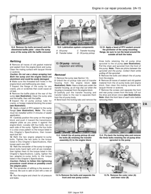 52
52 53
53 54
54 55
55 56
56 57
57 58
58 59
59 60
60 61
61 62
62 63
63 64
64 65
65 66
66 67
67 68
68 69
69 70
70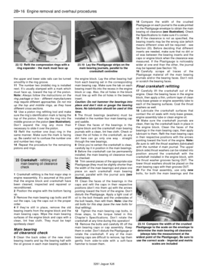 71
71 72
72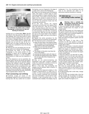 73
73 74
74 75
75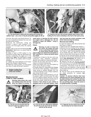 76
76 77
77 78
78 79
79 80
80 81
81 82
82 83
83 84
84 85
85 86
86 87
87 88
88 89
89 90
90 91
91 92
92 93
93 94
94 95
95 96
96 97
97 98
98 99
99 100
100 101
101 102
102 103
103 104
104 105
105 106
106 107
107 108
108 109
109 110
110 111
111 112
112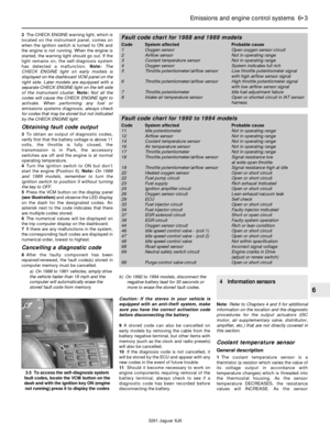 113
113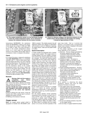 114
114 115
115 116
116 117
117 118
118 119
119 120
120 121
121 122
122 123
123 124
124 125
125 126
126 127
127 128
128 129
129 130
130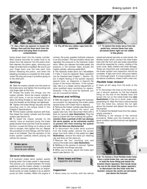 131
131 132
132 133
133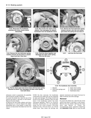 134
134 135
135 136
136 137
137 138
138 139
139 140
140 141
141 142
142 143
143 144
144 145
145 146
146 147
147 148
148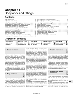 149
149 150
150 151
151 152
152 153
153 154
154 155
155 156
156 157
157 158
158 159
159 160
160 161
161 162
162 163
163 164
164 165
165 166
166 167
167 168
168 169
169 170
170 171
171 172
172 173
173 174
174 175
175 176
176 177
177 178
178 179
179 180
180 181
181 182
182 183
183 184
184 185
185 186
186 187
187 188
188 189
189 190
190 191
191 192
192 193
193 194
194 195
195 196
196 197
197 198
198 199
199 200
200 201
201 202
202 203
203 204
204 205
205 206
206 207
207 208
208 209
209 210
210 211
211 212
212 213
213 214
214 215
215 216
216 217
217 218
218 219
219 220
220 221
221 222
222 223
223 224
224 225
225 226
226