Page 25 of 44
01-125
Note:
No "ATS alarm" can be triggered via this output
Diagnostic Test Mode (DTM). To trigger a "ATS
alarm", perform the actuator test via the control
module for central locking page 01
-91
or a
function test page 01
-122
.
Pa
ge 25 of 44 Ultrasonic interior monitorin
g On Board Dia
gnostic
(OBD
)
11/20/2002 htt
p://127.0.0.1:8080/audi/servlet/Dis
play?action=Goto&t
yp
e=re
pair&id=AUDI.B5.BD04.01.4
Page 26 of 44

01-126
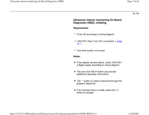
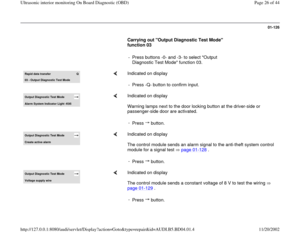
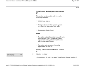
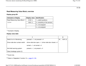
Carrying out "Output Diagnostic Test Mode"
function 03
- Press buttons -0- and -3- to select "Output
Diagnostic Test Mode" function 03. Rapid data transfer
Q
03 - Output Dia
gnostic Test Mode
Indicated on display
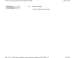
- Press -Q- button to confirm input.
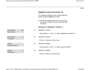
Output Diagnostic Test Mode Alarm S
ystem Indicator Li
ght -K95
Indicated on display
Warning lamps next to the door locking button at the driver-side or
passenger-side door are activated.
-
Press button.
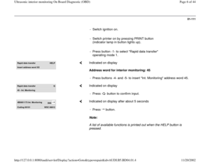
Output Diagnostic Test Mode Create active alarm
Indicated on display
The control module sends an alarm signal to the anti-theft system control
module for a signal test page 01
-128
.
-
Press button.
Output Diagnostic Test Mode Volta
ge suppl
y wire
Indicated on display
The control module sends a constant voltage of 8 V to test the wiring
page 01
-129
.
-
Press button.
Pa
ge 26 of 44 Ultrasonic interior monitorin
g On Board Dia
gnostic
(OBD
)
11/20/2002 htt
p://127.0.0.1:8080/audi/servlet/Dis
play?action=Goto&t
yp
e=re
pair&id=AUDI.B5.BD04.01.4
Page 27 of 44
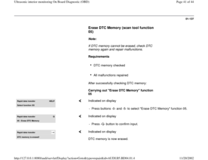
01-127
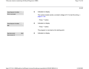
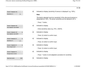
Output Diagnostic Test Mode Wire for c
ycle si
gnal
Indicated on display
The control module sends a constant voltage of 5 V to test the wiring
page 01
-130
.
-
Press button.
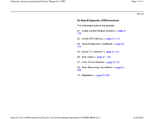
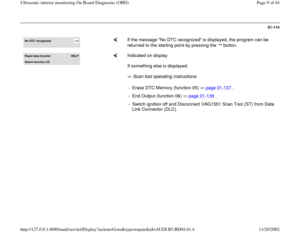
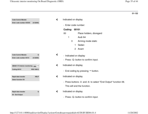
Output Diagnostic Test Mode END
Indicated on display
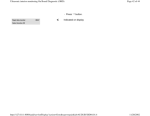
The program is now back at its starting point. -
Press button.
Rapid data transfer
HELP
Select function XX
Indicated on display
Pa
ge 27 of 44 Ultrasonic interior monitorin
g On Board Dia
gnostic
(OBD
)
11/20/2002 htt
p://127.0.0.1:8080/audi/servlet/Dis
play?action=Goto&t
yp
e=re
pair&id=AUDI.B5.BD04.01.4
Page 28 of 44
01-128
Testing alarm signal
- Switch ignition off and remove ignition key.
- Connect VAG1551 Scan Tool (ST) ( page 01
-
1 ), and press buttons -4- and -5- to select "Int.
Monitoring" address word 45.
- Close all doors and open one side window.
- Lock vehicle by reaching through open window.
The anti-theft system horn confirms this, but
warning lamps do not light up.
- Wait 30 seconds until anti-theft system is
armed.
- Perform Output Diagnostic Test Mode ( page
01
-124
) and select control element test "Create
active alarm."
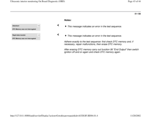
Notes:
It is also possible to test the alarm activation
signal without using the VAG1551 Scan Tool
(ST). To do this, carry out the first, third, fourth
and fifth procedure steps listed above.
Pa
ge 28 of 44 Ultrasonic interior monitorin
g On Board Dia
gnostic
(OBD
)
11/20/2002 htt
p://127.0.0.1:8080/audi/servlet/Dis
play?action=Goto&t
yp
e=re
pair&id=AUDI.B5.BD04.01.4
Page 29 of 44
The independent repair shop and the customer
can thereby test the functional capability of the
ultrasonic interior monitoring system.
Output Diagnostic Test Mode Create active alarm
Indicated on display
Specification: anti-theft system (turn signals and anti-theft horn) is
triggered.
Pa
ge 29 of 44 Ultrasonic interior monitorin
g On Board Dia
gnostic
(OBD
)
11/20/2002 htt
p://127.0.0.1:8080/audi/servlet/Dis
play?action=Goto&t
yp
e=re
pair&id=AUDI.B5.BD04.01.4
Page 30 of 44
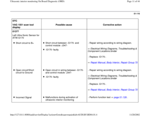
01-129
- Shut off alarm by unlocking vehicle.
- End Output Diagnostic Test Mode (DTM).
- Initiate On Board Diagnostic (OBD) for anti-theft
system.
- Erase DTC memory page 01
-137
.
Checking power supply wiring
- Remove both ultra-sound sensors.
Repair Manual, Body Interior, Repair Group
70, B
-pillar trim , removing and installing
- Disconnect electronic harness connectors.
- Perform Output Diagnostic Test Mode ( page
01
-124
) and select output test "Power supply
wiring."
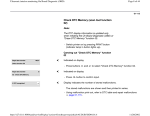
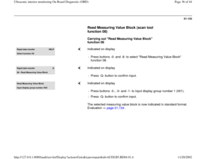
Output Diagnostic Test Mode Power suppl
y wirin
g
Indicated on display
- Using multimeter (Fluke 83 or equivalent), measure voltage at wiring
harness connector between terminal 2 (B+) and terminal 3 (GND).
Pa
ge 30 of 44 Ultrasonic interior monitorin
g On Board Dia
gnostic
(OBD
)
11/20/2002 htt
p://127.0.0.1:8080/audi/servlet/Dis
play?action=Goto&t
yp
e=re
pair&id=AUDI.B5.BD04.01.4
Page 31 of 44
Specification: 8 V
- End output Diagnostic Test Mode (DTM).
- Install ultra-sound sensors again
- Erase DTC memory (function 05) page 01
-137
.
- End output (function 06) page 01
-139
.
Pa
ge 31 of 44 Ultrasonic interior monitorin
g On Board Dia
gnostic
(OBD
)
11/20/2002 htt
p://127.0.0.1:8080/audi/servlet/Dis
play?action=Goto&t
yp
e=re
pair&id=AUDI.B5.BD04.01.4
Page 32 of 44
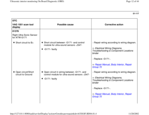
01-130
Checking wiring for pulse signal
- Remove both ultra-sound sensors.
Repair Manual, Body Interior, Repair Group
70, B
-pillar trim , removing and installing
- Disconnect electronic harness connectors.
- Perform Output Diagnostic Test Mode (DTM) (
page 01
-124
) and select control element test
"Signal pulse wire."
Output Diagnostic Test Mode Signal pulse wire
Indicated on display
- Using multimeter (Fluke 83 or equivalent), measure voltage at wiring
harness connector between terminal 1 (pulse signal) and terminal 3
(GND).
Specification: 5 V
- End Output Diagnostic Test Mode (DTM).
- Re-install ultra-sound sensors.
- Erase DTC memory (function 05) page 01
-137
.
- End Output (function 06) page 01
-139
.
Pa
ge 32 of 44 Ultrasonic interior monitorin
g On Board Dia
gnostic
(OBD
)
11/20/2002 htt
p://127.0.0.1:8080/audi/servlet/Dis
play?action=Goto&t
yp
e=re
pair&id=AUDI.B5.BD04.01.4
. To trigger a \"ATS
alarm\", perform the actuator test via the control
module for central locking")

 ( page 01
-
1 ), and press buttons -4- and -5- to select \"Int.
Mon")

.
- Initiate On Board Diagnostic (OBD) for anti-theft
system.
- Erase DTC memory p")
.
- Install ultra-sound sensors again
- Erase DTC memory (function 05) page 01
-137
.
- End output (function 06) page 01
-139
.
Pa")
