Page 1 of 44
01-108
Ultrasonic interior monitoring
On Board Diagnostic (OBD)
General Information
The ultrasonic interior monitoring system is only
offered in conjunction with the anti-theft system.
The security provided by the anti-theft system is
enhanced through addition of the ultrasonic
interior monitoring option.
Interior monitoring activates the anti-theft alarm
when unauthorized attempts are made to enter
the vehicle through the side windows.
Function
The ultrasonic interior monitoring system
consists of:
Control module for ultra-sound sensors -
J347-
Ultra-sound sensor, left for anti-theft warning
system -G170-
Ultra-sound sensor, right for anti-theft warning
system -G171-
Pa
ge 1 of 44 Ultrasonic interior monitorin
g On Board Dia
gnostic
(OBD
)
11/20/2002 htt
p://127.0.0.1:8080/audi/servlet/Dis
play?action=Goto&t
yp
e=re
pair&id=AUDI.B5.BD04.01.4
Page 2 of 44
Sensor for broken window glass rear left -G183-
(only for Avant)
Sensor for broken window glass rear right -
G184- (only for Avant)
Switch for passenger compartment monitoring -
E183-
Pa
ge 2 of 44 Ultrasonic interior monitorin
g On Board Dia
gnostic
(OBD
)
11/20/2002 htt
p://127.0.0.1:8080/audi/servlet/Dis
play?action=Goto&t
yp
e=re
pair&id=AUDI.B5.BD04.01.4
Page 3 of 44

01-109
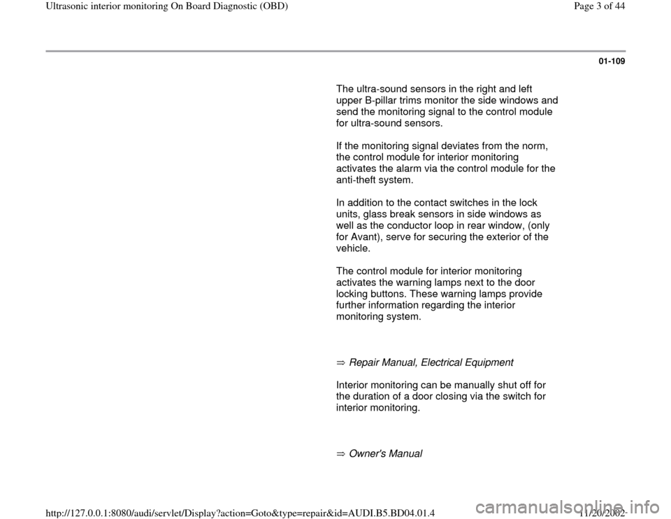
The ultra-sound sensors in the right and left
upper B-pillar trims monitor the side windows and
send the monitoring signal to the control module
for ultra-sound sensors.
If the monitoring signal deviates from the norm,
the control module for interior monitoring
activates the alarm via the control module for the
anti-theft system.
In addition to the contact switches in the lock
units, glass break sensors in side windows as
well as the conductor loop in rear window, (only
for Avant), serve for securing the exterior of the
vehicle.
The control module for interior monitoring
activates the warning lamps next to the door
locking buttons. These warning lamps provide
further information regarding the interior
monitoring system.
Repair Manual, Electrical Equipment Interior monitoring can be manually shut off for
the duration of a door closing via the switch for
interior monitoring.
Owner's Manual
Pa
ge 3 of 44 Ultrasonic interior monitorin
g On Board Dia
gnostic
(OBD
)
11/20/2002 htt
p://127.0.0.1:8080/audi/servlet/Dis
play?action=Goto&t
yp
e=re
pair&id=AUDI.B5.BD04.01.4
Page 11 of 44
01-116
DTC
VAG 1551 scan tool
display Possible cause
Corrective action
01377
Left Ultra-Sonic Sensor for
ATW-G170
Short circuit to B+
Short circuit between -G170- and
control module -J347-
-G170- faulty Electrical Wiring Diagrams, Troubleshooting &
Component Locations binder
Repair Manual, Body Interior, Repair Group 70
- Repair wiring according to wiring diagram.
- Replace -G170-.
Open circuit/Short
circuit to Ground
Open circuit in wiring between -G170-
and control module -J347-
-G170- faulty Electrical Wiring Diagrams, Troubleshooting &
Component Locations binder
Repair Manual, Body Interior, Repair Group 70
- Repair wiring according to wiring diagram.
- Replace -G170-.
Incorrect Signal
Malfunctions during activation of
ultrasonic interior monitoring - Perform function test page 01
-128
.Pa
ge 11 of 44 Ultrasonic interior monitorin
g On Board Dia
gnostic
(OBD
)
11/20/2002 htt
p://127.0.0.1:8080/audi/servlet/Dis
play?action=Goto&t
yp
e=re
pair&id=AUDI.B5.BD04.01.4
Page 12 of 44
01-117
DTC
VAG 1551 scan tool
display Possible cause
Corrective action
01378
Right Ultra-Sonic Sensor
for ATW-G171
Short circuit to B+
Short circuit between -G171- and control
module for ultra-sound sensors -J347-
-G171- faulty Electrical Wiring Diagrams,
Troubleshooting & Component Locations
binder
Repair Manual, Body Interior, Repair
Group 70
- Repair wiring according to wiring diagram.
- Replace -G171-.
Open circuit/Short
circuit to Ground
Open circuit in wiring between -G171- and
control module for ultra-sound sensors -J347-
-G171- faulty Electrical Wiring Diagrams,
Troubleshooting & Component Locations
binder
Repair Manual, Body Interior, Repair
Group 70
- Repair wiring according to wiring diagram.
- Replace -G171-.
Pa
ge 12 of 44 Ultrasonic interior monitorin
g On Board Dia
gnostic
(OBD
)
11/20/2002 htt
p://127.0.0.1:8080/audi/servlet/Dis
play?action=Goto&t
yp
e=re
pair&id=AUDI.B5.BD04.01.4
Page 14 of 44

01-118
DTC
VAG 1551 scan
tool display Possible cause
Corrective action
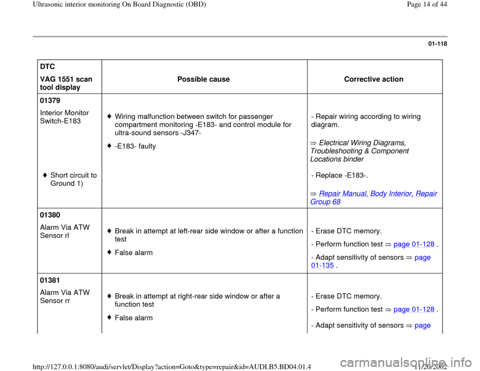
01379
Interior Monitor
Switch-E183
Wiring malfunction between switch for passenger
compartment monitoring -E183- and control module for
ultra-sound sensors -J347-
-E183- faulty Electrical Wiring Diagrams,
Troubleshooting & Component
Locations binder - Repair wiring according to wiring
diagram.
Short circuit to
Ground 1)
Repair Manual, Body Interior, Repair
Group 68
- Replace -E183-.
01380
Alarm Via ATW
Sensor rl
Break in attempt at left-rear side window or after a function
test
False alarm- Erase DTC memory.
- Perform function test page 01
-128
.
- Adapt sensitivity of sensors page 01
-135
.
01381
Alarm Via ATW
Sensor rr
Break in attempt at right-rear side window or after a
function test
False alarm- Erase DTC memory.
- Perform function test page 01
-128
.
- Adapt sensitivity of sensors page
Pa
ge 14 of 44 Ultrasonic interior monitorin
g On Board Dia
gnostic
(OBD
)
11/20/2002 htt
p://127.0.0.1:8080/audi/servlet/Dis
play?action=Goto&t
yp
e=re
pair&id=AUDI.B5.BD04.01.4
Page 16 of 44
01-119
DTC
VAG 1551 scan tool
display Possible cause
Corrective action
01382
Alarm Via ATW Sensor
fl
Break in attempt at left-front side window or after a
function test
False alarm- Erase DTC memory.
- Perform function test page 01
-
128
.
- Adapt sensitivity of sensors page 01
-135
.
01383
Alarm Via ATW Sensor
fr
Break in attempt at right-front side window or after a
function test
False alarm- Erase DTC memory.
- Perform function test page 01
-
128
.
- Adapt sensitivity of sensors page 01
-135
.
Pa
ge 16 of 44 Ultrasonic interior monitorin
g On Board Dia
gnostic
(OBD
)
11/20/2002 htt
p://127.0.0.1:8080/audi/servlet/Dis
play?action=Goto&t
yp
e=re
pair&id=AUDI.B5.BD04.01.4
Page 17 of 44

01-120
V.A.G 1551 Scan Tool display
Possible cause
Corrective action
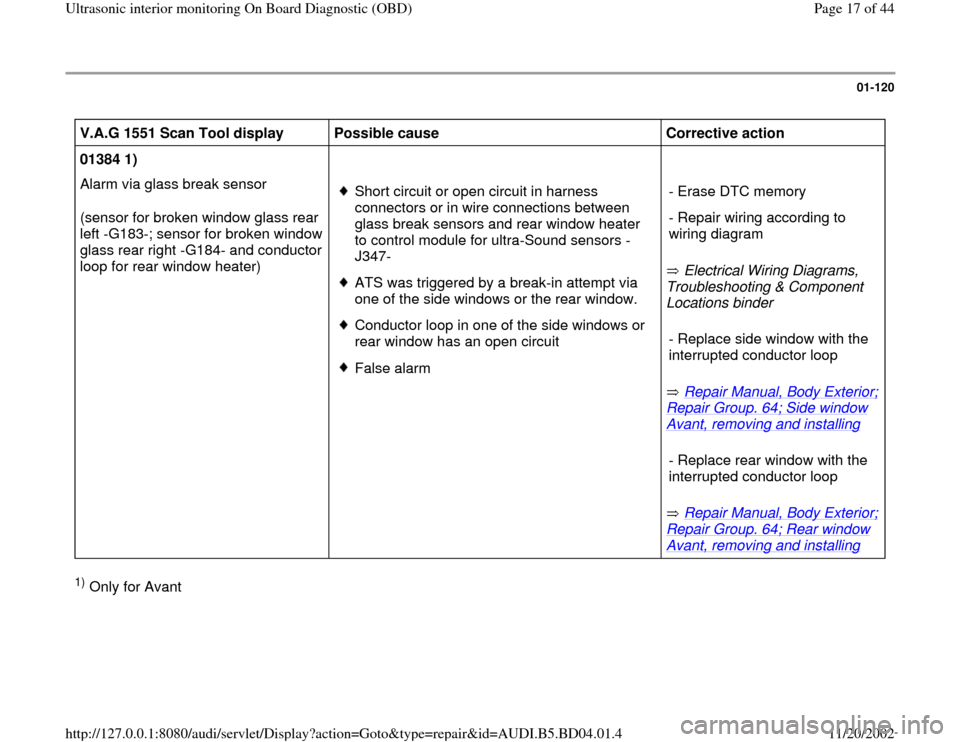
01384 1)
Alarm via glass break sensor
(sensor for broken window glass rear
left -G183-; sensor for broken window
glass rear right -G184- and conductor
loop for rear window heater)
Short circuit or open circuit in harness
connectors or in wire connections between
glass break sensors and rear window heater
to control module for ultra-Sound sensors -
J347- ATS was triggered by a break-in attempt via
one of the side windows or the rear window. Conductor loop in one of the side windows or
rear window has an open circuit False alarm Electrical Wiring Diagrams,
Troubleshooting & Component
Locations binder
Repair Manual, Body Exterior;
Repair Group. 64; Side window Avant, removing and installing
Repair Manual, Body Exterior;
Repair Group. 64; Rear window Avant, removing and installing
- Erase DTC memory
- Repair wiring according to
wiring diagram
- Replace side window with the
interrupted conductor loop - Replace rear window with the
interrupted conductor loop
1) Only for Avant
Pa
ge 17 of 44 Ultrasonic interior monitorin
g On Board Dia
gnostic
(OBD
)
11/20/2002 htt
p://127.0.0.1:8080/audi/servlet/Dis
play?action=Goto&t
yp
e=re
pair&id=AUDI.B5.BD04.01.4