1997 ACURA NSX torque
[x] Cancel search: torquePage 510 of 1503
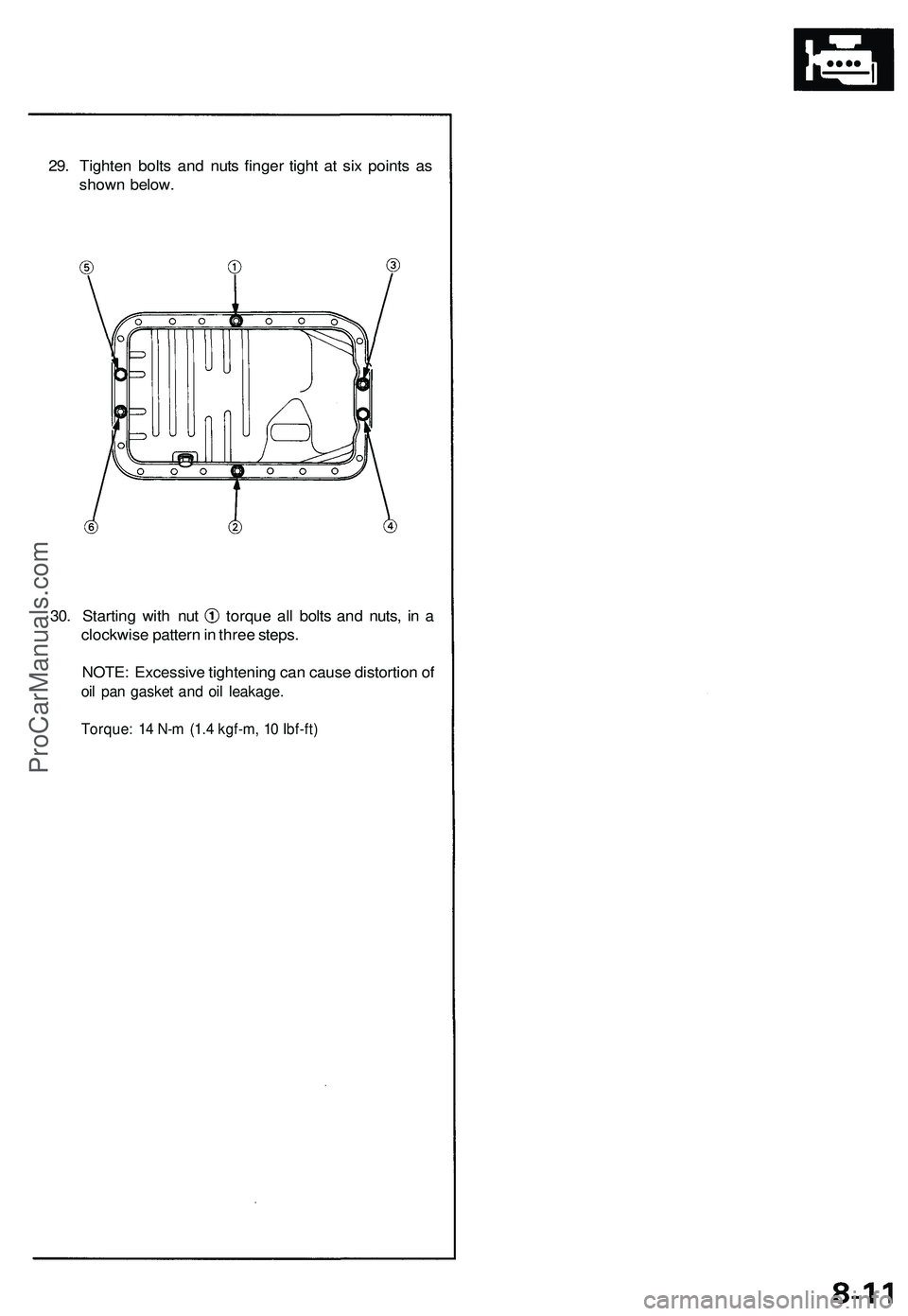
29. Tighten bolts and nuts finger tight at six points as
shown below.
30. Starting with nut torque all bolts and nuts, in a
clockwise pattern in three steps.
NOTE: Excessive tightening can cause distortion of
oil pan gasket and oil leakage.
Torque: 14 N-m (1.4 kgf-m, 10 Ibf-ft)ProCarManuals.com
Page 586 of 1503
PGM-FI System
System Description (cont'd)
3. Fuel Cut-off Control
During deceleration with the throttle valve closed, current to the fuel injectors is cut off to improve fuel economy at
speeds over 1,500 rpm.
Fuel cut-off action also takes place when engine speed exceeds 8,300 rpm, regardless of the position of the throttle
valve, to protect the engine from over-revving.
4. A/C Compressor Clutch Relay
When the ECM receives a demand for cooling from the air conditioning system, it delays the compressor from being
energized, and enriches the mixture to assure smooth translation to the A/C mode.
5. Evaporative Emission (EVAP) Purge Control Solenoid Valve
When the engine coolant temperature is below 153°F (67°C), the ECM controls the EVAP purge control solenoid valve
which cuts vacuum to the EVAP purge control canister diaphragm.
6. Intake Air Bypass (IAB) Control Solenoid Valve
When the engine speed is below 4,800 rpm, the IAB control solenoid valve is activated by a signal from the ECM. Intake
air then flows through the smaller chamber, and high torque is delivered. To increase air flow at engine speeds higher
than 4,800 rpm, the solenoid valve is deactivated by the ECM, and the intake air flows through the larger chamber.
7. Exhaust Gas Recirculation (EGR) Control Solenoid Valve
When the EGR is required for control of oxides of nitrogen (NOx) emissions, the ECM supplies ground to the EGR
control solenoid valve which supplies regulated vacuum to the EGR valve.
ECM Fail-safe/Back-up Functions
1. Fail-Safe Function
When an abnormality occurs in a signal from a sensor, the ECM ignores that signal and assumes a pre-programmed
valve for that sensor that allows the engine to continue to run.
2. Back-up Function
When an abnormality occurs in the ECM itself, the fuel injectors are controlled by a back-up circuit independent of the
system in order to permit minimal driving.
3. Self-diagnosis Function [Malfunction Indicator Lamp (MIL)]
When an abnormality occurs in a signal from a sensor, the ECM lights the MIL and stores the diagnostic trouble code
in erasable memory. When the ignition is initially turned on, the ECM supplies ground for the MIL for two seconds to
check the MIL bulb condition.
4. Two Trip Detection Method
To prevent false indications, the Two Trip Detection Method is used for the H02S, fuel metering-related, idle control
system, ECT sensor, EGR system self-diagnostic functions and EVAP control system. When an abnormality occurs,
the ECM stores it in its memory. When the same abnormality recurs after the ignition switch is turned OFF and ON (II)
again, the ECM informs the driver by lighting the MIL.
However, to ease troubleshooting, this function is cancelled when you short the service check connector. The MIL will
then blink immediately when an abnormality occurs.
5. Two (or three) Driving Cycle Detection Method
A "Driving Cycle" consists of starting the engine, beginning closed loop operation, and stopping the engine. If misfir-
ing that increases emissions or EVAP control system malfunction is detected during two consecutive driving cycles,
or TWC deterioration is detected during three consecutive driving cycles, the ECM turns the MIL on.
However,
to
ease
troubleshooting,
this
function
is
cancelled when
you
short
the
service check connector.
The MIL
will
then blink immediately when an abnormality occurs.ProCarManuals.com
Page 628 of 1503
Intake Air System
Intake Air Bypass (IAB) Control System
Description
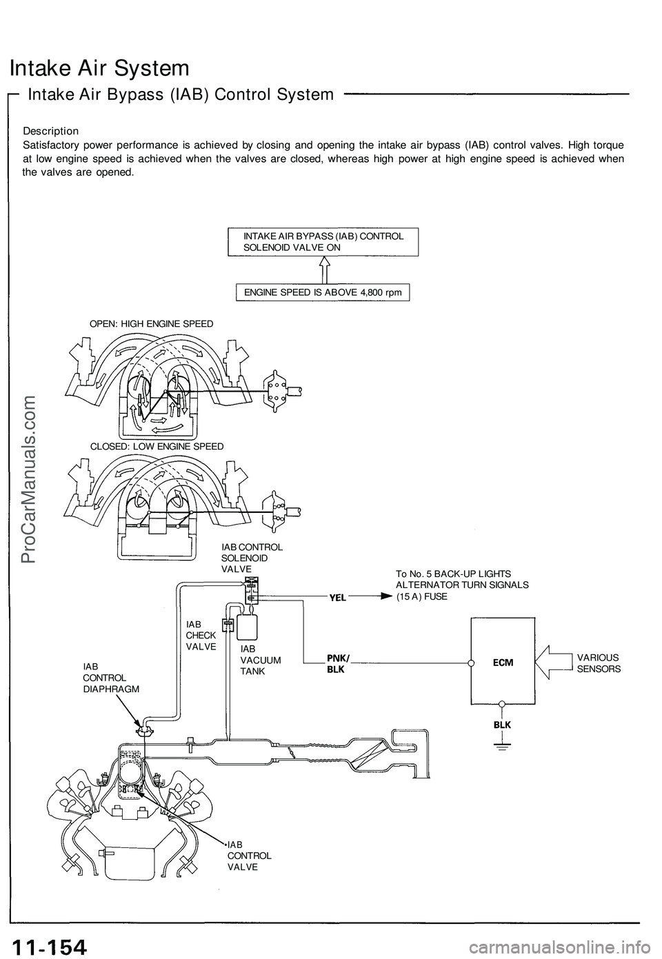
Satisfactory power performance is achieved by closing and opening the intake air bypass (IAB) control valves. High torque
at low engine speed is achieved when the valves are closed, whereas high power at high engine speed is achieved when
the valves are opened.
INTAKE AIR BYPASS (IAB) CONTROL
SOLENOID VALVE ON
ENGINE SPEED IS ABOVE 4,800 rpm
OPEN: HIGH ENGINE SPEED
CLOSED: LOW ENGINE SPEED
IAB CONTROL
SOLENOID
VALVE
To No. 5 BACK-UP LIGHTS
ALTERNATOR TURN SIGNALS
(15 A) FUSE
IAB
CONTROL
DIAPHRAGM
•IAB
CONTROL
VALVE
IAB
CHECK
VALVE
IAB
VACUUM
TANK
VARIOUS
SENSORSProCarManuals.com
Page 701 of 1503
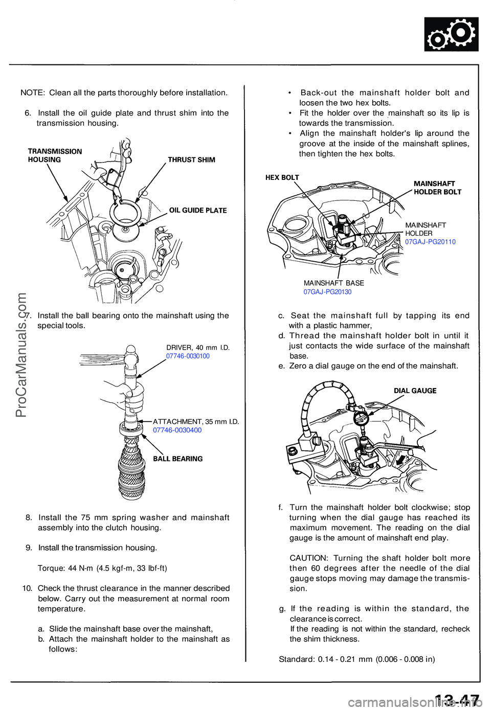
NOTE: Clea n al l th e part s thoroughl y befor e installation .
6 . Instal l th e oi l guid e plat e an d thrus t shi m int o th e
transmissio n housing .
DRIVER, 4 0 m m I.D .07746 -003010 0
7. Instal l th e bal l bearin g ont o th e mainshaf t usin g th e
specia l tools .
ATTACHMENT , 3 5 m m I.D .
0774 6-003040 0
8. Instal l th e 7 5 m m sprin g washe r an d mainshaf t
assembl y int o th e clutc h housing .
9. Instal l th e transmissio n housing .
Torque: 4 4 N- m (4. 5 kgf-m , 3 3 Ibf-ft )
10. Chec k th e thrus t clearanc e in th e manne r describe d
below . Carr y ou t th e measuremen t a t norma l roo m
temperature .
a . Slid e th e mainshaf t bas e ove r th e mainshaft ,
b . Attac h th e mainshaf t holde r t o th e mainshaf t a s
follows : f
. Tur n th e mainshaf t holde r bol t clockwise ; sto p
turnin g whe n th e dia l gaug e ha s reache d it s
maximu m movement . Th e readin g o n th e dia l
gaug e is th e amoun t o f mainshaf t en d play .
CAUTION : Turnin g th e shaf t holde r bol t mor e
the n 6 0 degree s afte r th e needl e o f th e dia l
gaug e stop s movin g ma y damag e th e transmis -sion.
g. I f th e readin g i s withi n th e standard , th e
clearanc e is correct .
I f th e readin g i s no t withi n th e standard , rechec k
th e shi m thickness .
Standard : 0.1 4 - 0.2 1 m m (0.00 6 - 0.00 8 in )
•
Back-ou t th e mainshaf t holde r bol t an d
loose n th e tw o he x bolts .
• Fi t th e holde r ove r th e mainshaf t s o it s li p i s
toward s th e transmission .
• Alig n th e mainshaf t holder' s li p aroun d th e
groov e a t th e insid e o f th e mainshaf t splines ,
the n tighte n th e he x bolts .
MAINSHAF T BAS E07GA J-PG2013 0
MAINSHAF THOLDER07GAJ-PG2011 0
c. Sea t th e mainshaf t ful l b y tappin g it s en d
wit h a plasti c hammer ,
d. Threa d th e mainshaf t holde r bol t i n unti l i t
jus t contact s th e wid e surfac e o f th e mainshaf t
base.
e. Zer o a dia l gaug e o n th e en d o f th e mainshaft .
ProCarManuals.com
Page 713 of 1503
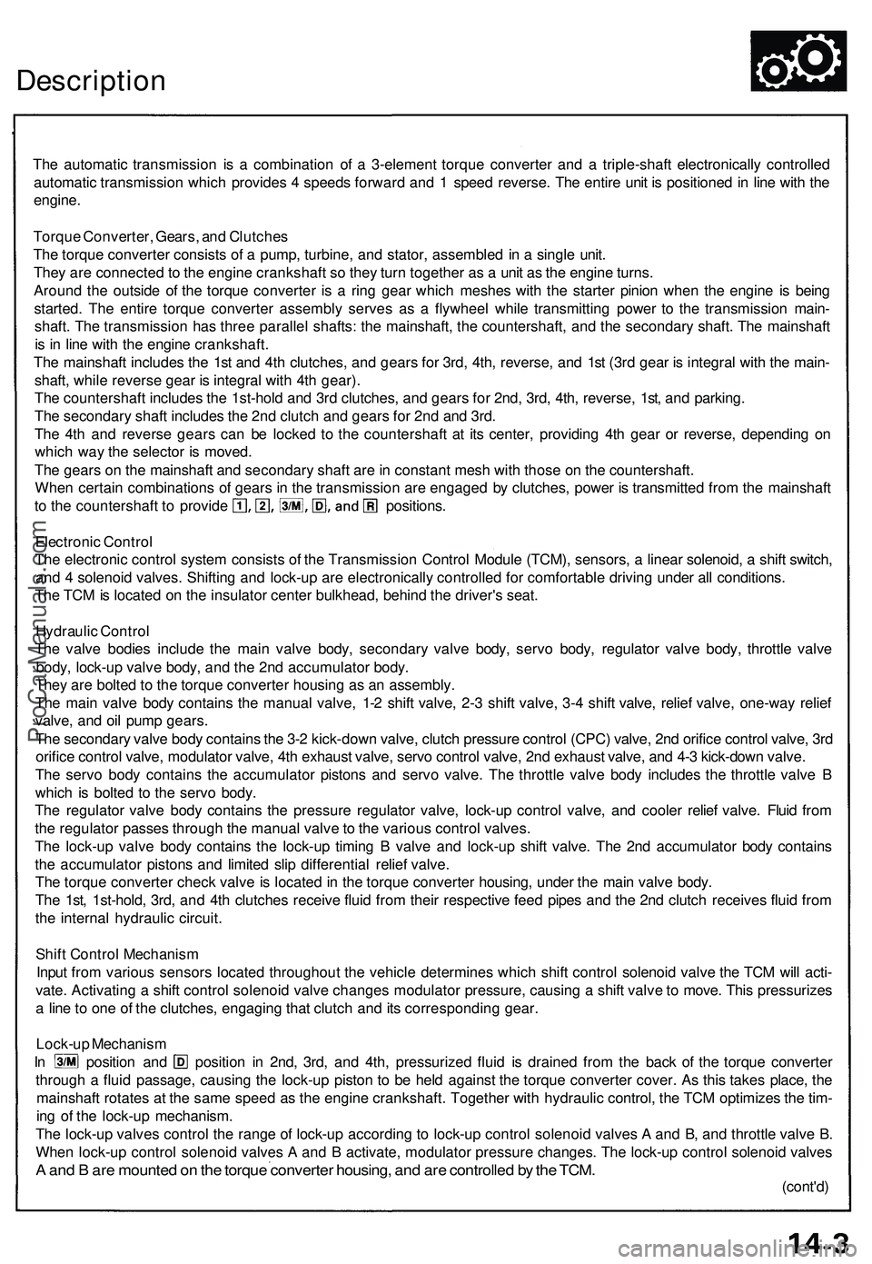
Description
The automatic transmission is a combination of a 3-element torque converter and a triple-shaft electronically controlled
automatic transmission which provides 4 speeds forward and 1 speed reverse. The entire unit is positioned in line with the
engine.
Torque Converter, Gears, and Clutches
The torque converter consists of a pump, turbine, and stator, assembled in a single unit.
They are connected to the engine crankshaft so they turn together as a unit as the engine turns.
Around the outside of the torque converter is a ring gear which meshes with the starter pinion when the engine is being
started. The entire torque converter assembly serves as a flywheel while transmitting power to the transmission main-
shaft. The transmission has three parallel shafts: the mainshaft, the countershaft, and the secondary shaft. The mainshaft
is in line with the engine crankshaft.
The mainshaft includes the 1st and 4th clutches, and gears for 3rd, 4th, reverse, and 1st (3rd gear is integral with the main-
shaft, while reverse gear is integral with 4th gear).
The countershaft includes the 1st-hold and 3rd clutches, and gears for 2nd, 3rd, 4th, reverse, 1st, and parking.
The secondary shaft includes the 2nd clutch and gears for 2nd and 3rd.
The 4th and reverse gears can be locked to the countershaft at its center, providing 4th gear or reverse, depending on
which way the selector is moved.
The gears on the mainshaft and secondary shaft are in constant mesh with those on the countershaft.
When certain combinations of gears in the transmission are engaged by clutches, power is transmitted from the mainshaft
to the countershaft to provide positions.
Electronic Control
The electronic control system consists of the Transmission Control Module (TCM), sensors, a linear solenoid, a shift switch,
and 4 solenoid valves. Shifting and lock-up are electronically controlled for comfortable driving under all conditions.
The TCM is located on the insulator center bulkhead, behind the driver's seat.
Hydraulic Control
The valve bodies include the main valve body, secondary valve body, servo body, regulator valve body, throttle valve
body, lock-up valve body, and the 2nd accumulator body.
They are bolted to the torque converter housing as an assembly.
The main valve body contains the manual valve, 1-2 shift valve, 2-3 shift valve, 3-4 shift valve, relief valve, one-way relief
valve, and oil pump gears.
The secondary valve body contains the 3-2 kick-down valve, clutch pressure control (CPC) valve, 2nd orifice control valve, 3rd
orifice control valve, modulator valve, 4th exhaust valve, servo control valve, 2nd exhaust valve, and 4-3 kick-down valve.
The servo body contains the accumulator pistons and servo valve. The throttle valve body includes the throttle valve B
which is bolted to the servo body.
The regulator valve body contains the pressure regulator valve, lock-up control valve, and cooler relief valve. Fluid from
the regulator passes through the manual valve to the various control valves.
The lock-up valve body contains the lock-up timing B valve and lock-up shift valve. The 2nd accumulator body contains
the accumulator pistons and limited slip differential relief valve.
The torque converter check valve is located in the torque converter housing, under the main valve body.
The 1st, 1st-hold, 3rd, and 4th clutches receive fluid from their respective feed pipes and the 2nd clutch receives fluid from
the internal hydraulic circuit.
Shift Control Mechanism
Input from various sensors located throughout the vehicle determines which shift control solenoid valve the TCM will acti-
vate. Activating a shift control solenoid valve changes modulator pressure, causing a shift valve to move. This pressurizes
a line to one of the clutches, engaging that clutch and its corresponding gear.
Lock-up Mechanism
In position and position in 2nd, 3rd, and 4th, pressurized fluid is drained from the back of the torque converter
through a fluid passage, causing the lock-up piston to be held against the torque converter cover. As this takes place, the
mainshaft rotates at the same speed as the engine crankshaft. Together with hydraulic control, the TCM optimizes the tim-
ing of the lock-up mechanism.
The lock-up valves control the range of lock-up according to lock-up control solenoid valves A and B, and throttle valve B.
When lock-up control solenoid valves A and B activate, modulator pressure changes. The lock-up control solenoid valves
A and B are mounted on the torque converter housing, and are controlled by the TCM.
(cont'd)ProCarManuals.com
Page 715 of 1503
![ACURA NSX 1997 Service Repair Manual
TORQUE CONVERTER
LOCK-UP CONTROL
SOLENOID VALVE
ASSEMBLY
4TH CLUTCH
1ST CLUTCH
1ST-HOLD CLUTCH
ATF COOLER
DIFFERENTIAL ASSEMBLY
[LIMITED SLIP DIFFERENTIAL (LSD)]
2ND CLUTCH
3RD CLUTCHProCa](/manual-img/32/56989/w960_56989-714.png "ACURA NSX 1997 Service Repair Manual
TORQUE CONVERTER
LOCK-UP CONTROL
SOLENOID VALVE
ASSEMBLY
4TH CLUTCH
1ST CLUTCH
1ST-HOLD CLUTCH
ATF COOLER
DIFFERENTIAL ASSEMBLY
[LIMITED SLIP DIFFERENTIAL (LSD)]
2ND CLUTCH
3RD CLUTCHProCa")
TORQUE CONVERTER
LOCK-UP CONTROL
SOLENOID VALVE
ASSEMBLY
4TH CLUTCH
1ST CLUTCH
1ST-HOLD CLUTCH
ATF COOLER
DIFFERENTIAL ASSEMBLY
[LIMITED SLIP DIFFERENTIAL (LSD)]
2ND CLUTCH
3RD CLUTCHProCarManuals.com
Page 725 of 1503
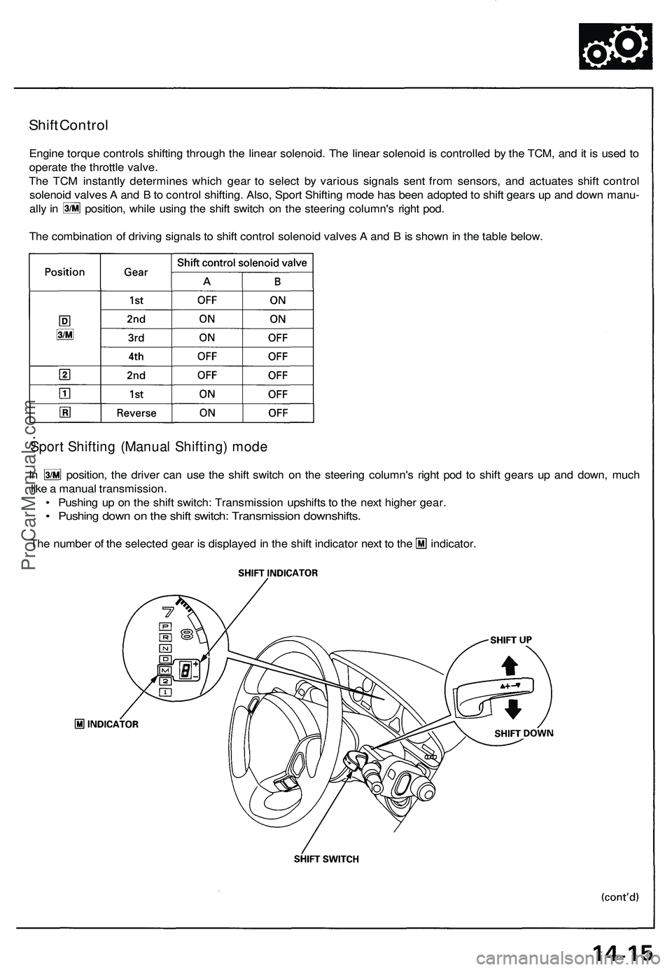
Shift Control
Engine torque controls shifting through the linear solenoid. The linear solenoid is controlled by the TCM, and it is used to
operate the throttle valve.
The TCM instantly determines which gear to select by various signals sent from sensors, and actuates shift control
solenoid valves A and B to control shifting. Also, Sport Shifting mode has been adopted to shift gears up and down manu-
ally in position, while using the shift switch on the steering column's right pod.
The combination of driving signals to shift control solenoid valves A and B is shown in the table below.
Sport Shifting (Manual Shifting) mode
In position, the driver can use the shift switch on the steering column's right pod to shift gears up and down, much
like a manual transmission.
• Pushing up on the shift switch: Transmission upshifts to the next higher gear.
• Pushing down on the shift switch: Transmission downshifts.
The number of the selected gear is displayed in the shift indicator next to the indicator.ProCarManuals.com
Page 727 of 1503
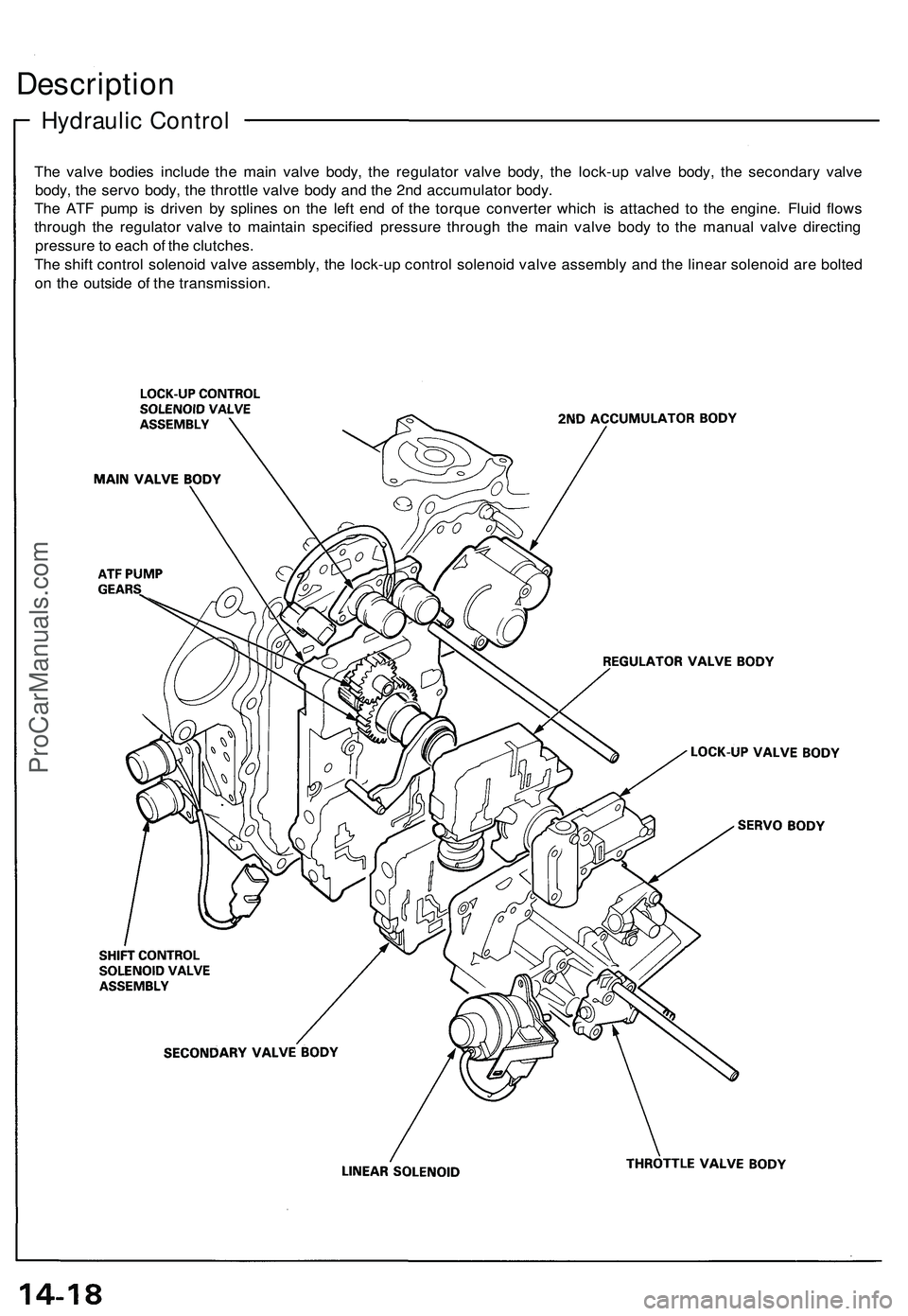
Hydraulic Control
Description
The valve bodies include the main valve body, the regulator valve body, the lock-up valve body, the secondary valve
body, the servo body, the throttle valve body and the 2nd accumulator body.
The ATF pump is driven by splines on the left end of the torque converter which is attached to the engine. Fluid flows
through the regulator valve to maintain specified pressure through the main valve body to the manual valve directing
pressure to each of the clutches.
The shift control solenoid valve assembly, the lock-up control solenoid valve assembly and the linear solenoid are bolted
on the outside of the transmission.ProCarManuals.com