Page 995 of 1503
Pushrod Clearanc e Adjustmen t
Brake Booste r
NOTE: Maste r cylinde r pushrod-to-pisto n clearanc e
mus t b e checke d an d adjustment s made , i f necessary ,
befor e installin g maste r cylinder .
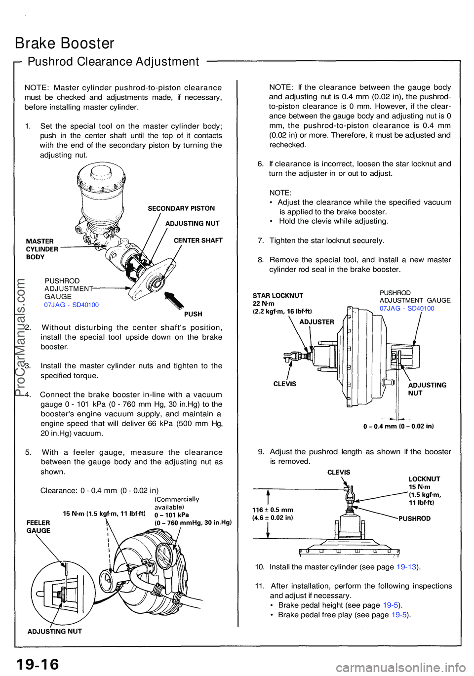
1 . Se t th e specia l too l o n th e maste r cylinde r body ;
pus h i n th e cente r shaf t unti l th e to p o f i t contact s
wit h th e en d o f th e secondar y pisto n b y turnin g th e
adjustin g nut . NOTE
: I f th e clearanc e betwee n th e gaug e bod y
and adjustin g nu t i s 0. 4 m m (0.0 2 in) , th e pushrod -
to-piston clearanc e i s 0 mm . However , i f th e clear -
anc e betwee n th e gaug e bod y an d adjustin g nu t i s 0
mm , th e pushrod-to-pisto n clearanc e i s 0. 4 m m
(0.0 2 in ) o r more . Therefore , i t mus t b e adjuste d an d
rechecked .
6. I f clearanc e i s incorrect , loose n th e sta r locknu t an d
tur n th e adjuste r i n o r ou t t o adjust .
NOTE:
• Adjus t th e clearanc e whil e th e specifie d vacuu m
i s applie d to th e brak e booster .
• Hol d th e clevi s whil e adjusting .
7 . Tighte n th e sta r locknu t securely .
8 . Remov e th e specia l tool , an d instal l a ne w maste r
cylinde r ro d sea l i n th e brak e booster.
PUSHRO D
ADJUSTMEN T GAUG E
07JA G - SD4010 0
PUSHRODADJUSTMEN TGAUGE07JAG - SD4010 0
2. Withou t disturbin g th e cente r shaft' s position ,
instal l th e specia l too l upsid e dow n o n th e brak e
booster .
3. Instal l th e maste r cylinde r nut s an d tighte n t o th e
specifie d torque .
4 . Connec t th e brak e booste r in-lin e wit h a vacuu m
gaug e 0 - 10 1 kP a ( 0 - 76 0 m m Hg , 3 0 in.Hg ) t o th e
booster' s engin e vacuu m supply , an d maintai n a
engin e spee d tha t wil l delive r 6 6 kP a (50 0 m m Hg ,
2 0 in.Hg ) vacuum .
5 . Wit h a feele r gauge , measur e th e clearanc e
betwee n th e gaug e bod y an d th e adjustin g nu t a s
shown .
Clearance : 0 - 0. 4 m m (0 - 0.0 2 in )
9. Adjus t th e pushro d lengt h a s show n i f th e booste r
is removed .
10 . Instal l th e maste r cylinde r (se e pag e 19-13 ).
11 . Afte r installation , perfor m th e followin g inspection s
an d adjus t i f necessary .
• Brak e peda l heigh t (se e pag e 19-5 ).
• Brak e peda l fre e pla y (se e pag e 19-5 ).
ProCarManuals.com
Page 996 of 1503
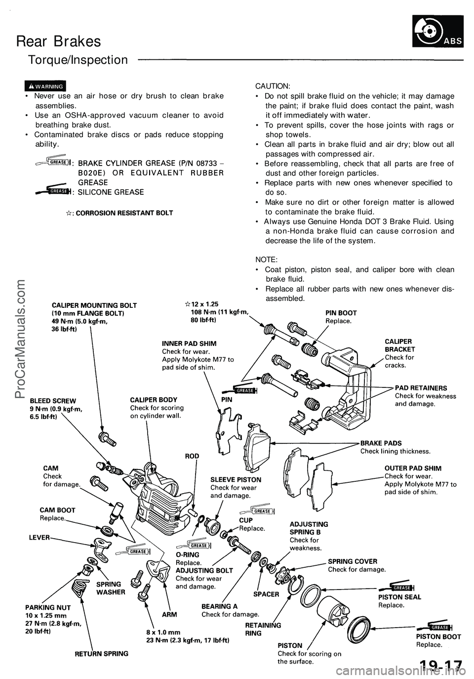
Rear Brakes
Torque/Inspection
• Never use an air hose or dry brush to clean brake
assemblies.
• Use an OSHA-approved vacuum cleaner to avoid
breathing brake dust.
• Contaminated brake discs or pads reduce stopping
ability.
CAUTION:
• Do not spill brake fluid on the vehicle; it may damage
the paint; if brake fluid does contact the paint, wash
it off immediately with water.
• To prevent spills, cover the hose joints with rags or
shop towels.
• Clean all parts in brake fluid and air dry; blow out all
passages with compressed air.
• Before reassembling, check that all parts are free of
dust and other foreign particles.
• Replace parts with new ones whenever specified to
do so.
• Make sure no dirt or other foreign matter is allowed
to contaminate the brake fluid.
• Always use Genuine Honda DOT 3 Brake Fluid. Using
a non-Honda brake fluid can cause corrosion and
decrease the life of the system.
NOTE:
• Coat piston, piston seal, and caliper bore with clean
brake fluid.
• Replace all rubber parts with new ones whenever dis-
assembled.ProCarManuals.com
Page 999 of 1503
Inspection/Replacement (cont'd)
Rear Brake Pads
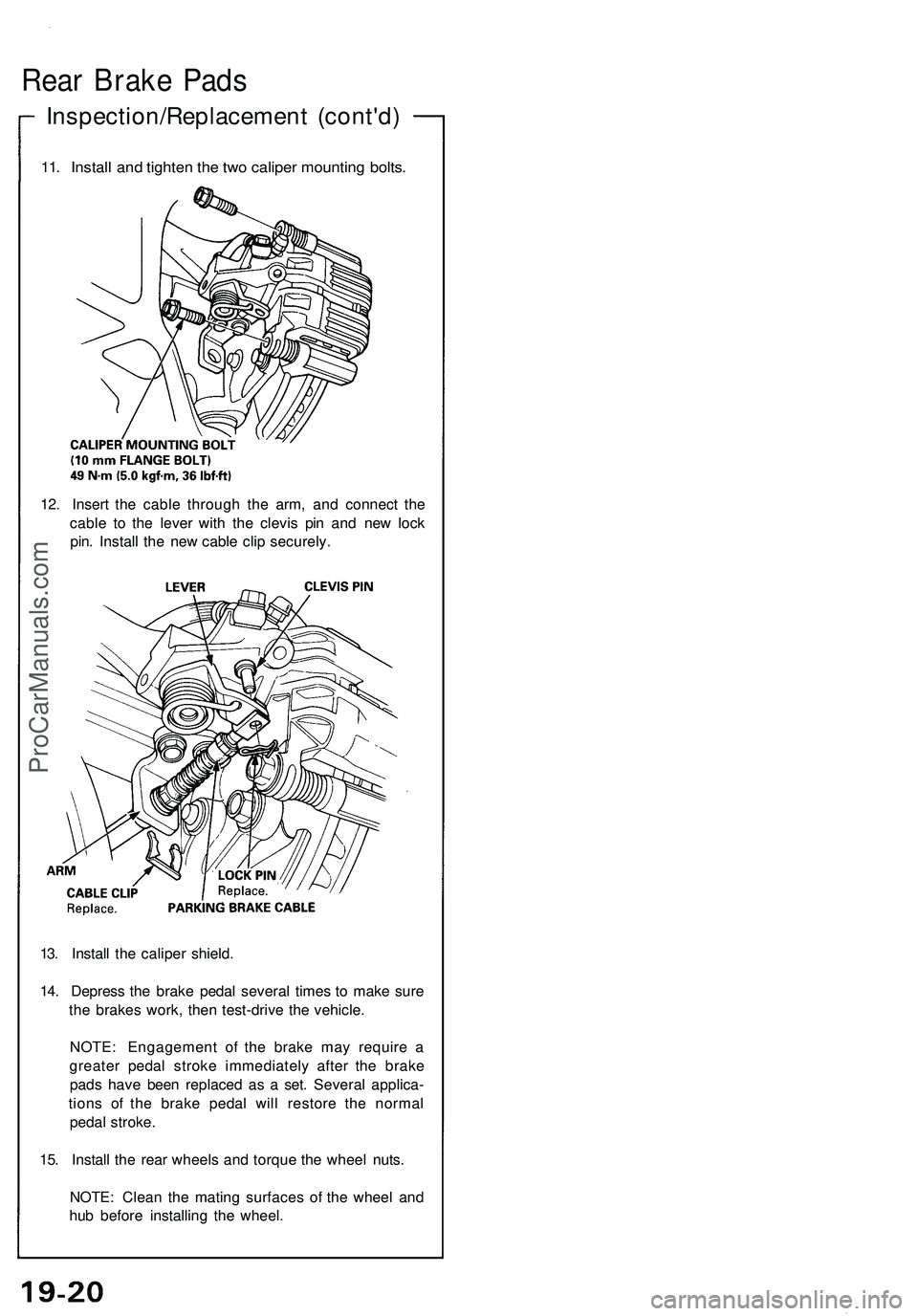
11. Install and tighten the two caliper mounting bolts.
12. Insert the cable through the arm, and connect the
cable to the lever with the clevis pin and new lock
pin. Install the new cable clip securely.
13. Install the caliper shield.
14. Depress the brake pedal several times to make sure
the brakes work, then test-drive the vehicle.
NOTE: Engagement of the brake may require a
greater pedal stroke immediately after the brake
pads have been replaced as a set. Several applica-
tions of the brake pedal will restore the normal
pedal stroke.
15. Install the rear wheels and torque the wheel nuts.
NOTE: Clean the mating surfaces of the wheel and
hub before installing the wheel.ProCarManuals.com
Page 1036 of 1503
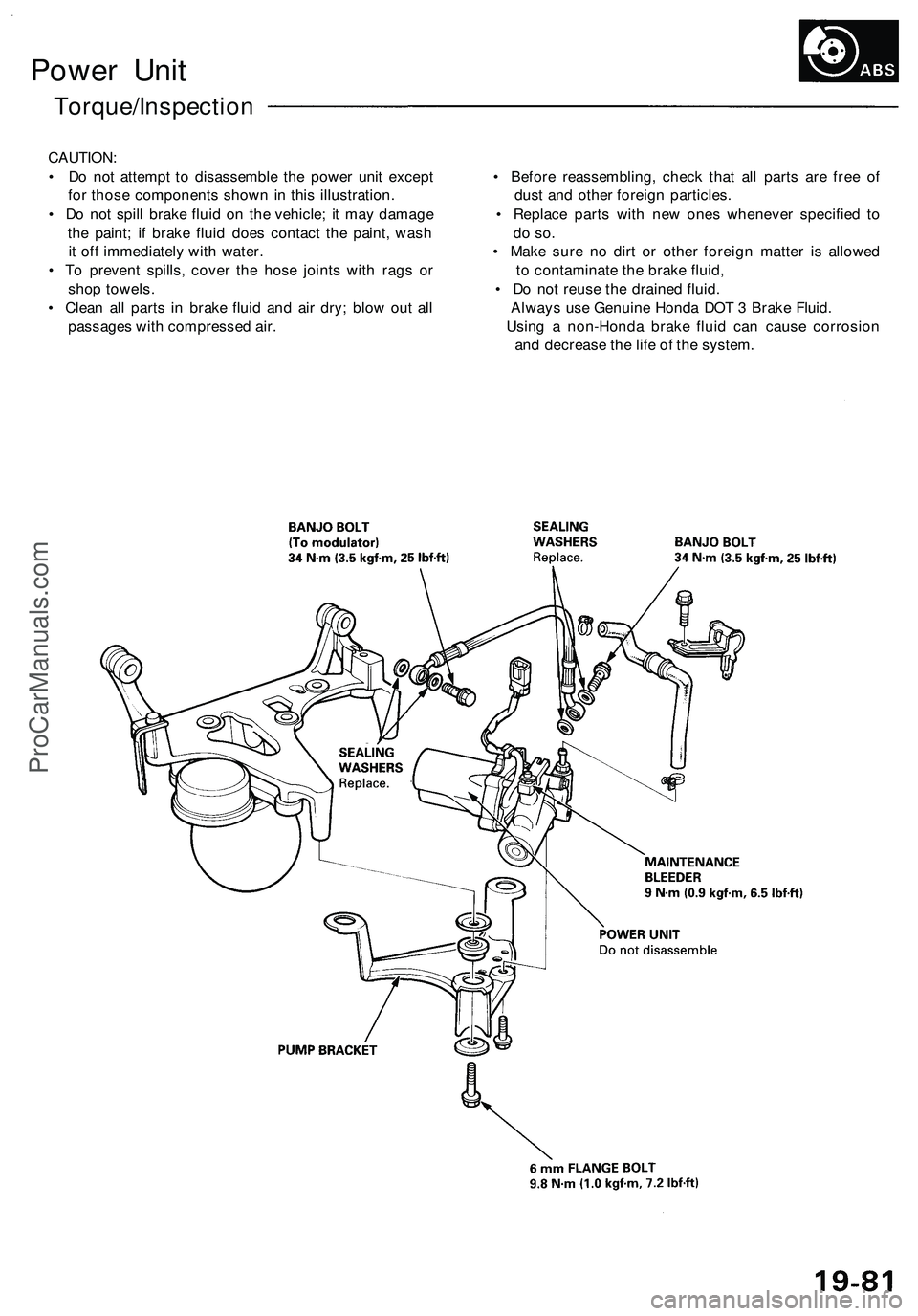
Power Unit
Torque/Inspection
CAUTION:
• Do not attempt to disassemble the power unit except • Before reassembling, check that all parts are free of
for those components shown in this illustration. dust and other foreign particles.
• Do not spill brake fluid on the vehicle; it may damage • Replace parts with new ones whenever specified to
the paint; if brake fluid does contact the paint, wash do so.
it off immediately with water. • Make sure no dirt or other foreign matter is allowed
• To prevent spills, cover the hose joints with rags or to contaminate the brake fluid,
shop towels. • Do not reuse the drained fluid.
• Clean all parts in brake fluid and air dry; blow out all Always use Genuine Honda DOT 3 Brake Fluid.
passages with compressed air. Using a non-Honda brake fluid can cause corrosion
and decrease the life of the system.ProCarManuals.com
Page 1130 of 1503
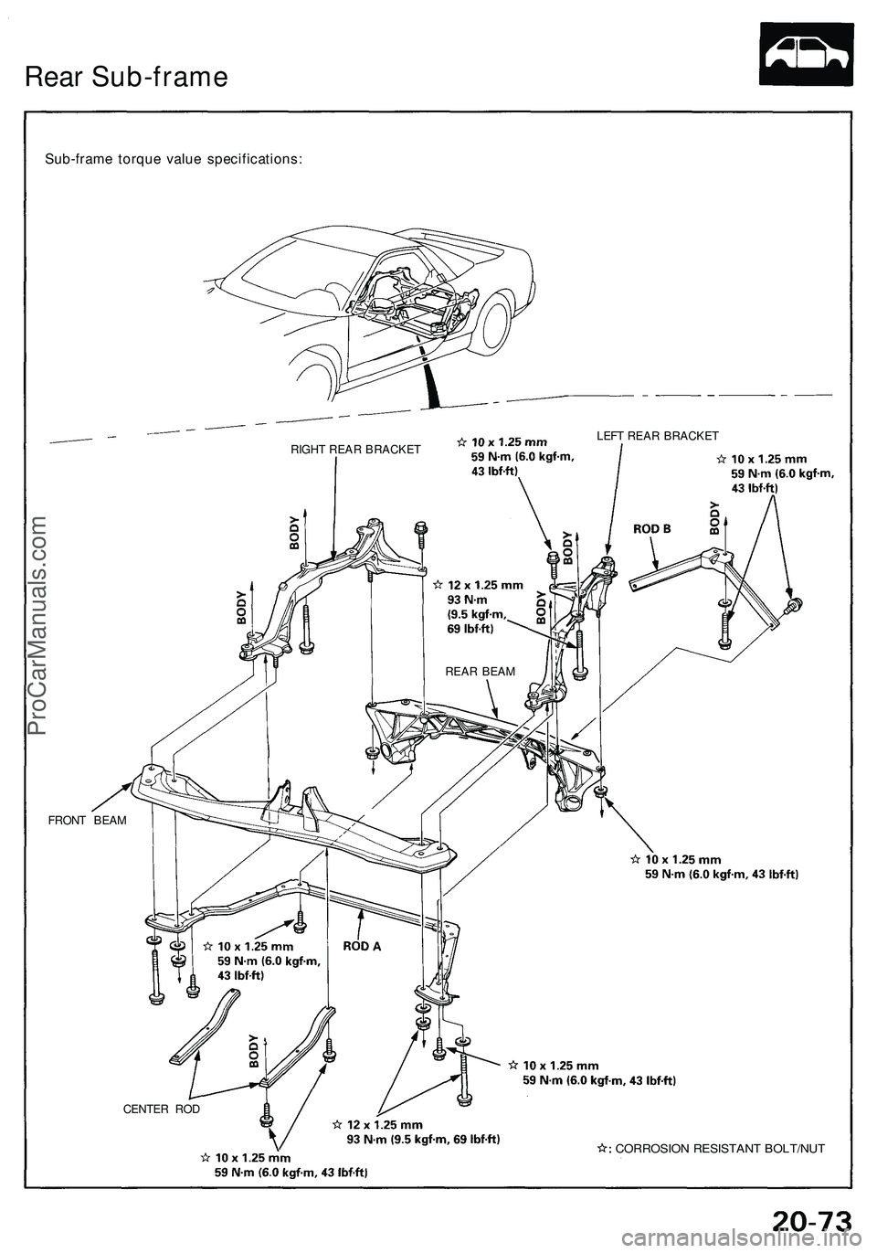
Rear Sub-frame
Sub-frame torque value specifications:
RIGHT REAR BRACKET
LEFT REAR BRACKET
FRONT BEAM
CENTER ROD
CORROSION RESISTANT BOLT/NUT
REAR BEAMProCarManuals.com
Page 1267 of 1503
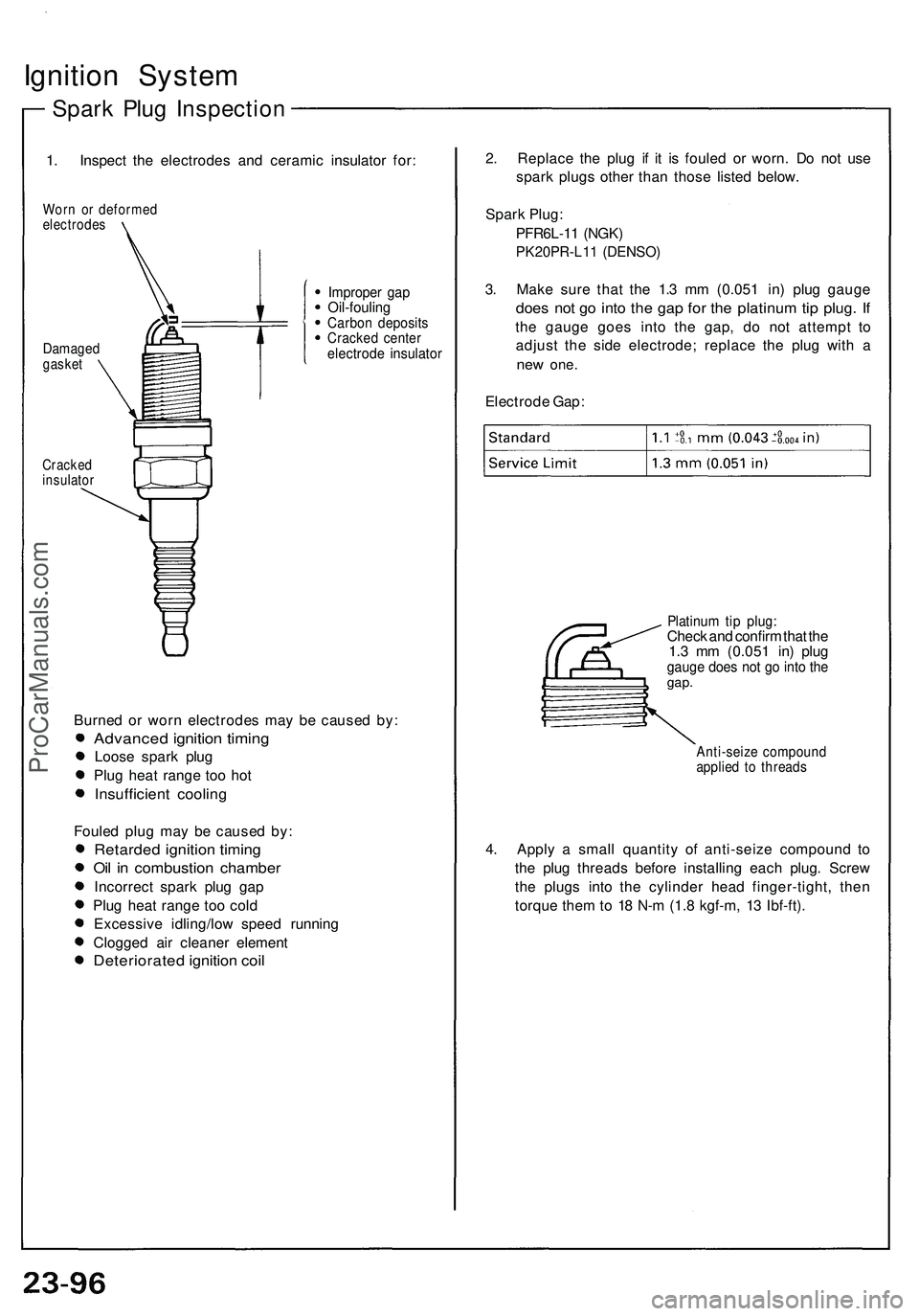
Ignition System
Spark Plug Inspection
1. Inspect the electrodes and ceramic insulator for:
Worn or deformed
electrodes
Cracked
insulator
Burned or worn electrodes may be caused by:
Advanced ignition timing
Loose spark plug
Plug heat range too hot
Insufficient cooling
Fouled plug may be caused by:
Retarded ignition timing
Oil in combustion chamber
Incorrect spark plug gap
Plug heat range too cold
Excessive idling/low speed running
Clogged air cleaner element
Deteriorated ignition coil
2. Replace the plug if it is fouled or worn. Do not use
spark plugs other than those listed below.
Spark Plug:
PFR6L-11 (NGK)
PK20PR-L11 (DENSO)
3. Make sure that the 1.3 mm (0.051 in) plug gauge
does not go into the gap for the platinum tip plug. If
the gauge goes into the gap, do not attempt to
adjust the side electrode; replace the plug with a
new
one.
Electrode Gap:
Platinum tip plug:
Check and confirm that the
1.3 mm (0.051 in) plug
gauge does not go into the
gap.
Anti-seize compound
applied to threads
4. Apply a small quantity of anti-seize compound to
the plug threads before installing each plug. Screw
the plugs into the cylinder head finger-tight, then
torque them to 18 N-m (1.8 kgf-m, 13 Ibf-ft).
Improper gap
Oil-fouling
Carbon deposits
Cracked center
electrode insulator
Damaged
gasketProCarManuals.com