Page 874 of 1202

REPLACEMENT
1. REMOVE FRONT WHEEL
Remove the wheel and temporarily fasten the disc with hub
nuts.
2. INSPECT PAD LININ")
BR0RO-03
BR4213
BR4214
BR0272
- BRAKEFRONT BRAKE PAD
BR-21
1996 TERCEL (RM440U)
REPLACEMENT
1. REMOVE FRONT WHEEL
Remove the wheel and temporarily fasten the disc with hub
nuts.
2. INSPECT PAD LINING THICKNESS
Check the pad thickness through the caliper inspection hole
and replace the pads if they are not within the specification.
Minimum thickness: 1.0 mm (0.039 in.)
3. REMOVE CALIPER
(a) Remove the 2 installation bolts from the torque plate.
(b) Remove the caliper and suspend it securely.
HINT:
Do not disconnect the flexible hose.
4. REMOVE THESE PARTS:
(a) 2 brake pads
(b) 3 anti-squeal shims
(c) Pad wear indicator plate
(d) 4 pad support plates
NOTICE:
The support plates can be used again provided that they
have sufficient rebound, no deformation, cracks or wear,
and have had all rust, dirt and foreign particles cleaned off.
5. CHECK DISC THICKNESS AND RUNOUT
(See page BR-26)
6. INSTALL 4 PAD SUPPORT PLATES
7. INSTALL NEW PADS
NOTICE:
When replacing worn pads, the anti-squeal shims and
wear indicator plates must be replaced together with the
pads.
(a) Install a pad wear indicator plate on the inner pad.
(b) Apply disc brake grease to the anti-squeal shims (See
page BR-23).
(c) Install the 2 anti-squeal shims on the outer pad.
(d) Install the anti-squeal shim on the inner pad
Page 875 of 1202
N00746
BR-22
- BRAKEFRONT BRAKE PAD
1996 TERCEL (RM440U)
(e) Install inner pad with the pad wear indicator plate facing
upward.
(f) Install outer pad.
NOTICE:
There should be no oil or grease adhering to the friction
surfaces of the pads or the disc.
8. INSTALL CALIPER
(a) Draw out a small amount of brake fluid from the reservoir.
(b) Press in the piston with a hammer handle or an equiva-
lent.
HINT:
If the piston is difficult to push in, loosen the bleeder plug and
push in the piston while letting some brake fluid escape.
(c) Install the caliper.
(d) Install and torque the 2 installation bolts.
Torque: 25 N´m (255 kgf´cm, 18 ft´lbf)
9. INSTALL FRONT WHEEL
10. CHECK THAT FLUID LEVEL IS AT MAX LINE
Page 884 of 1202
BR4387
BR3027
SST
BR0370
- BRAKEREAR DRUM BRAKE
BR-31
1996 TERCEL (RM440U)
(d) Using pliers, disconnect the parking brake cable from the
parking brake lever and remove the rear shoe.
6. REMOVE AUTOMATIC ADJUSTING LEVER AND
PARKING BRAKE LEVER
(a) Remove the E-ring.
(b) Remove the automatic adjusting lever.
(c) Remove the C-washer.
(d) Remove the parking brake lever.
7. REMOVE WHEEL CYLINDER
(a) Using SST, disconnect the brake line. Use a container to
catch the brake fluid.
SST 09751-3601 1
Torque: 15 N´m (155 kgf´cm, 11 ft´lbf)
(b) Remove the 2 bolts and the wheel cylinder.
Torque: 10 N´m (100 kgf´cm, 7 ft´lbf)
8. DISASSEMBLE WHEEL CYLINDER
Remove the these parts from the wheel cylinder.
�2 boots
�2 pistons
�2 piston cups
�Spring
Page 909 of 1202
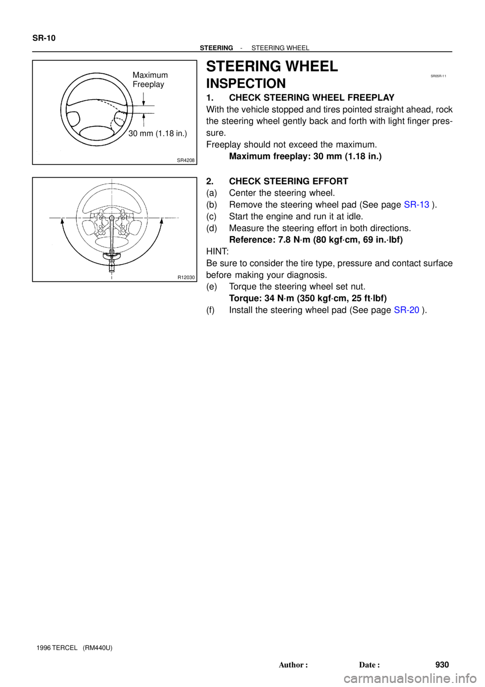
SR4208
Maximum
Freeplay
30 mm (1.18 in.)SR05R-1 1
R12030
SR-10
- STEERINGSTEERING WHEEL
930 Author�: Date�:
1996 TERCEL (RM440U)
STEERING WHEEL
INSPECTION
1. CHECK STEERING WHEEL FREEPLAY
With the vehicle stopped and tires pointed straight ahead, rock
the steering wheel gently back and forth with light finger pres-
sure.
Freeplay should not exceed the maximum.
Maximum freeplay: 30 mm (1.18 in.)
2. CHECK STEERING EFFORT
(a) Center the steering wheel.
(b) Remove the steering wheel pad (See page SR-13).
(c) Start the engine and run it at idle.
(d) Measure the steering effort in both directions.
Reference: 7.8 N´m (80 kgf´cm, 69 in.´lbf)
HINT:
Be sure to consider the tire type, pressure and contact surface
before making your diagnosis.
(e) Torque the steering wheel set nut.
Torque: 34 N´m (350 kgf´cm, 25 ft´lbf)
(f) Install the steering wheel pad (See page SR-20).
Page 920 of 1202

11. CENTER SPIRAL CABLE
(a) Check that the front wheels are facing straight ahead.
(b) Turn the cable count")
W01455
Torx ScrewScrew Case
- STEERINGNON-TIL T STEERING COLUMN
SR-21
1996 TERCEL (RM440U)
11. CENTER SPIRAL CABLE
(a) Check that the front wheels are facing straight ahead.
(b) Turn the cable counterclockwise by hand until it becomes
harder to turn the cable.
(c) Then rotate the cable clockwise about 2.5 turns to align
the green marks.
HINT:
The spiral cable turns clockwise about 2.5 turns to either left or
right of the center.
12. INSTALL STEERING WHEEL
(a) Align the matchmarks on the steering wheel and main
shaft assembly.
(b) Torque the steering wheel set nut.
Torque: 34 N´m (350 kgf´cm, 25 ft´lbf)
(c) Connect the connector.
13. w/ Airbag:
INSTALL STEERING WHEEL PAD
NOTICE:
�Make sure the wheel pad is installed with the speci-
fied torque.
�If the wheel pad has been dropped, or there are
cracks, dents or other defects in the case or connec-
tor, replace the wheel pad with a new one.
�When installing the wheel pad, take care that the wir-
ings do not interfere with other parts and that they are
not pinched between other parts.
(a) Connect the airbag connector.
(b) Install the wheel pad after confirming that the circumfer-
ence groove of the torx screws are caught on the screw
case.
(c) Using a torx socket wrench, torque the 2 screws.
Torque: 8.8 N´m (90 kgf´cm, 78 in.´lbf)
14. w/o Airbag:
INSTALL STEERING WHEEL PAD
15. CHECK STEERING WHEEL CENTER POINT
Page 944 of 1202
SR0KW-02
- STEERINGMANUAL STEERING GEAR
SR-45
1996 TERCEL (RM440U)
INSTALLATION
1. INSTALL MANUAL STEERING GEAR ASSEMBLY
Install the gear assembly from the LH of the vehicle.
2. INSTALL 2 GROMMETS AND BRACKETS
Torque the 2 bolts and nuts.
Torque: 58 N´m (590 kgf´cm, 43 ft´lbf)
3. CONNECT SLIDING YOKE (See page SR-20)
4. INSTALL COLUMN HOLE COVER
Torque the 4 nuts.
Torque: 4.9 N´m (50 kgf´cm, 43 in.´lbf)
5. CONNECT RH AND LH TIE ROD ENDS (See page SA-10)
6. PLACE FRONT WHEELS FACING STRAIGHT AHEAD
HINT:
Do it with the front of the vehicle jacked up.
7. w/ Airbag:
CENTER SPIRAL CABLE (See page SR-20)
8. INSTALL STEERING WHEEL
(a) Install the wheel at straight-ahead position.
(b) Temporarily tighten the wheel set nut.
(c) Connect the connector.
9. CHECK STEERING WHEEL CENTER POINT
10. w/ Airbag:
TORQUE STEERING WHEEL SET NUT
Torque: 34 N´m (350 kgf´cm, 25 ft´lbf)
11. w/ Airbag:
INSTALL STEERING WHEEL PAD (See page SR-20)
12. CHECK FRONT WHEEL ALIGNMENT (See page SA-4)
Page 959 of 1202
 SR-60
- STEERINGPOWER STEERING GEAR
1996 TERCEL (RM440U)
15. INSTALL RH AND LH CLAW WASHERS AND RA")
R07337
Rack Groove
R11031
SST
Fulcrum
Length
R10934
Brass
Bar
F05319
SR4273
0 - 3 mm
(0 - 0.12 in.) SR-60
- STEERINGPOWER STEERING GEAR
1996 TERCEL (RM440U)
15. INSTALL RH AND LH CLAW WASHERS AND RACK
ENDS
(a) Install a new washer, and temporarily tighten the rack
end.
HINT:
Align the claws of the washer with the steering rack grooves.
(b) Using a spanner, hold the steering rack steadily and using
SST, torque the rack end.
SST 09922-10010
Torque: 51 N´m (520 kgf´cm, 18 ft´lbf)
NOTICE:
Use SST 09922-10010 in the direction shown in the illustra-
tion.
HINT:
Use a torque wrench with a fulcrum length of 345 mm (13.58
in.).
(c) Using a brass bar and a hammer, stake the washer.
NOTICE:
Avoid any impact on the rack.
16. INSTALL RH AND LH RACK BOOTS, CLAMPS AND
CLIPS
(a) Ensure that the steering rack hole is not clogged with
grease.
HINT:
If the hole is clogged, the pressure inside the boot will change
after it is assembled and the steering wheel is turned.
(b) Install the boot.
NOTICE:
Be careful not to damage or twist the boots.
(c) Tighten a new clamp, as shown in the illustration.
Page 962 of 1202

9. INSTALL FRONT EXHAUST PIPE
(a) Connect the 2 rings.
(b) Install the bolt and clamp over a new gasket.
Torque: 19 N´m (190 kgf´cm, 14 ft�")
- STEERINGPOWER STEERING GEAR
SR-63
1996 TERCEL (RM440U)
9. INSTALL FRONT EXHAUST PIPE
(a) Connect the 2 rings.
(b) Install the bolt and clamp over a new gasket.
Torque: 19 N´m (190 kgf´cm, 14 ft´lbf)
(c) Install the 2 bolts and compression springs over a new
gasket.
Torque: 62 N´m (630 kgf´cm, 46 ft´lbf)
10. INSTALL OXYGEN SENSOR
Install the sensor.
Torque: 44 N´m (450 kgf´cm, 32 ft´lbf)
11. CONNECT SLIDING YOKE (See page SR-20)
12. INSTALL COLUMN HOLE COVER
Torque the 2 bolts and nut.
Torque: 4.9 N´m (50 kgf´cm, 43 in.´lbf)
13. CONNECT RH AND LH TIE ROD ENDS
(See page SA-10)
14. PLACE FRONT WHEELS FACING STRAIGHT AHEAD
HINT:
Do it with the front of the vehicle jacked up.
15. w/ Airbag:
CENTER SPIRAL CABLE (See page SR-20)
16. w/ Airbag:
INSTALL STEERING WHEEL
(a) Install the wheel at straight-ahead position.
(b) Temporarily tighten the wheel set nut.
(c) Connect the connector.
17. BLEED POWER STEERING SYSTEM
(See page SR-5)
18. CHECK STEERING WHEEL CENTER POINT
19. w/ Airbag:
TORQUE STEERING WHEEL SET NUT
Torque: 34 N´m (350 kgf´cm, 25 ft´lbf)
20. w/ Airbag:
INSTALL STEERING WHEEL PAD (See page SR-20)
21. CHECK FRONT WHEEL ALIGNMENT
(See page SA-4)

(e) Install inner pad with the pad wear indicator plate facing
upward.
(f) Install outer pad.
NOTICE:
There should be no oil or grease adheri")

(d) Using pliers, disconnect the parking brake cable from the
parking brake lever and remove the rear shoe.
6. REMOVE AUTOM")

INSTALLATION
1. INSTALL MANUAL STEERING GEAR ASSEMBLY
Install the gear assembly from the LH of the vehicle.
2. INSTALL 2 GROMMETS A")