Page 165 of 1202
SS0M3-10
- SERVICE SPECIFICATIONSBRAKE
SS-35
1996 TERCEL (RM440U)
TORQUE SPECIFICATION
Part tightenedN´mkgf´cmft´lbf
Master cylinder x Piston stopper bolt101007
Master cylinder x Reservoir1.717.515.2 in.´lbf
Master cylinder x Brake booster131309
Brake line union nut1515511
Brake booster clevis lock nut2526019
Brake booster x Pedal bracket1414510
Front disc brake caliper installation bolt2525518
Bleeding plug8.38574 in.´lbf
Front disc brake torque plate x Steering knuckle8890065
Front disc brake caliper x Flexible hose3031022
Rear drum brake wheel cylinder x Backing plate101007
ABS actuator assembly x Body1919514
ABS actuator x ABS actuator bracket assembly5.45548 in.´lbf
ABS actuator x ABS actuator No. 3 bracket1919514
Front speed sensor x Steering knuckle8.08271 in.´lbf
Front speed sensor wire harness clamp installation bolt5.05144 in.´lbf
Rear speed sensor x Axle beam8.08271 in.´lbf
Rear speed sensor wire harness clamp installation bolt5.05144 in.´lbf
Page 166 of 1202

SS0N1-03
SS-36
- SERVICE SPECIFICATIONSSTEERING
166 Author�: Date�:
1996 TERCEL (RM440U)
STEERING
SERVICE DATA
ON-VEHICLE INSPECTION
Steering wheel freeplayMaximum30 mm (1.18 in.)
Drive belt tension New belt140 - 180 lbf Drive belt tension New belt
Used belt
140 180 lbf
80 - 120 lbf
Maximum rise of oil level5 mm (0.20 in.)
Oil pressure at idle speed with valve closed Minimum6,374 kPa (65 kgf/cm2, 925 psi)
Steering effort at idle speedMaximum7.8 N´m (80 kgf´cm, 69 in.lbf)
PS VANE PUMP
Rotor shaft bushing oil clearance STD0.01 - 0.03 mm (0.0004 - 0.0012 in.) Rotor shaft bushing oil clearance STD
Maximum
0.01 0.03 mm (0.0004 0.0012 in.)
0.07 mm (0.0028 in.)
Vane plate heightMinimum8.0 mm (0.315 in.)
Vane plate thickness Minimum1.77 mm (0.0697 in.)
Vane plate lengthMinimum14.97 mm (0.5894 in.)
Vane plate to rotor groove clearanceMaximum0.03 mm (0.0012 in.)
Vane plate length Pump rotor and cam ring mark Vane late length Pum rotor and cam ring mark
None14.996 - 14.998 mm (0.59039 - 0.59047 in.)None
1
14.996 - 14.998 mm (0.59039 - 0.59047 in.)
14.994 - 14.996 mm (0.59032 - 0.59039 in.)1
2
14.994 14.996 mm (0.59032 0.59039 in.)
14.992 - 14.994 mm (0.59024 - 0.59032 in.)2
3
14.992 14.994 mm (0.59024 0.59032 in.)
14.990 - 14.992 mm (0.59016 - 0.59024 in.)3
4
14.990 14.992 mm (0.59016 0.59024 in.)
14.988 - 14.990 mm (0.59008 - 0.59016 in.)
Spring free length36 - 38 mm (1.42 - 1.49 in.)
Vane pump rotating torqueMaximum0.3 N´m (2.8 kgf´cm, 2.4 in.´lbf) or less
MANUAL STEERING GEAR
Steering rack runout Maximum0.30 mm (0.0118 in.)
Pinion preload Turning0.23 - 0.32 N´m (2.3 - 3.3 kgf´cm, 2.0 - 2.9 in.lbf)
Total preload Turning0.6 - 1.2 N´m (6 - 12 kgf´cm, 5.2 - 10.4 in.´lbf)
PS GEAR
Steering rack runout Maximum0.30 mm (0.0118 in.)
Measure oil clearance STD0.050 - 0.083 mm (0.00197 - 0.00327 in.) Measure oil clearance STD
Maximum
0.050 0.083 mm (0.00197 0.00327 in.)
0.125 mm (0.00492 in.)
Total preload Turning0.8 - 1.4 N´m (8 - 14 kgf´cm, 6.9 - 12.2 in.´lbf)
Page 167 of 1202

SS0N2-05
- SERVICE SPECIFICATIONSSTEERING
SS-37
1996 TERCEL (RM440U)
TORQUE SPECIFICATION
Part tightenedN´mkgf´cmft´lbf
STEERING COLUMN
Steering support x Column tube5.45548 in.´lbf
Control valve shaft x Sliding yoke2526019
Steering main shaft x Sliding yoke2526019
Steering column assembly set nut2526019
Steering wheel set nut3435025
Steering wheel pad set screw8.89078 in.´lbf
PS VANE PUMP
Pressure port union x Front housing6970051
Suction port union x Front housing131309
Pressure feed tube x Pressure port union5455040
PS vane pump pulley set nut4344032
PS vane pump assembly set nut Bolt A4344032 PS vane um assembly set nut Bolt A
Bolt B
43
39
440
400
32
30
MANUAL STEERING GEAR
Pinion bearing adjusting screw lock nut for use with SST
for use without SST85
11 3871
1,15063
83
Rack guide spring cap lock nut for use with SST
for use without SST41
56419
57530
42
Rack x Rack end for use with SST
for use without SST43
59434
60031
43
Tie rod end lock nut4748035
Manual steering gear bracket x Body5859043
Pinion shaft x Sliding yoke2526019
Steering main shaft x Sliding yoke2526019
Column hole cover x Body4.95043 in.´lbf
PS GEAR
Cylinder end stopper5960043
Self-locking nut5960043
Rack housing cap5960043
Rack guide spring cap lock nut for use with SST
for use without SST31
44316
45023
33
Rack x Rack end for use with SST
for use without SST43
59434
60031
43
Tie rod end lock nut4748035
Turn pressure tube union nut for use with SST
for use without SST20
25203
25015
18
Air control valve2930022
PS gear bracket x Body5859043
Engine rear mount insulator Bolt A6465047 Engine rear mount insulator Bolt A
Bolt B
64
78
650
800
47
58
Engine rear mount bracket x Transaxle4849035
Front exhaust pipe x Exhaust manifold6263046
Front exhaust pipe clamp1919014
Front exhaust pipe x Oxygen sensor4445032
Page 169 of 1202
SS061-41
- SERVICE SPECIFICATIONSSUPPLEMENTAL RESTRAINT SYSTEM
SS-39
169 Author�: Date�:
1996 TERCEL (RM440U)
SUPPLEMENTAL RESTRAINT SYSTEM
TORQUE SPECIFICATION
Part tightenedN´mkgf´cmft´lbf
Steering wheel3435025
Steering wheel pad8.89078 in.´lbf
Front passenger airbag assembly1919514
Airbag sensor assembly2020014
Page 512 of 1202
P20750
P20480
SST
P20545
EM9412
EM7333
EM-90
- ENGINE MECHANICALCYLINDER BLOCK
1996 TERCEL (RM440U)
15. INSTALL RH ENGINE MOUNTING BRACKET
Torque: 58 N´m (590 kgf´cm, 43 ft´lbf)
16. INSTALL KNOCK SENSOR
Using SST, install the knock sensor.
SST 09816-30010
Torque: 45 N´m (450 kgf´cm, 33 ft´lbf)
17. INSTALL GENERATOR BRACKET
Torque: 24 N´m (240 kgf´cm, 18 ft´lbf)
18. INSTALL WATER PUMP WITH WATER INLET PIPE
19. INSTALL OIL DIPSTICK GUIDE AND GENERATOR AD-
JUSTING BAR
20. INSTALL CYLINDER HEAD
21. INSTALL TIMING BELT AND PULLEYS
22. REMOVE ENGINE STAND
23. INSTALL REAR END PLATE
Torque: 10 N´m (100 kgf´cm, 7 ft´lbf)
24. M/T:
INSTALL FLYWHEEL
(a) Apply adhesive to 2 or 3 threads of new mounting bolt
end.
Adhesive:
Part No. 08833-00070, THREE BOND 1324 or
equivalent
Page 513 of 1202
EM9410
1
2 3
45
6
- ENGINE MECHANICALCYLINDER BLOCK
EM-91
1996 TERCEL (RM440U)
(b) Install the flywheel on the crankshaft.
(c) Install and uniformly tighten the mounting bolts, in several
passes, in the sequence shown.
Torque: 90 N´m (900 kgf´cm, 65 ft´lbf)
25. A/T:
INSTALL DRIVE PLATE (See step 24)
26. M/T:
INSTALL CLUTCH DISC AND COVER
Page 713 of 1202

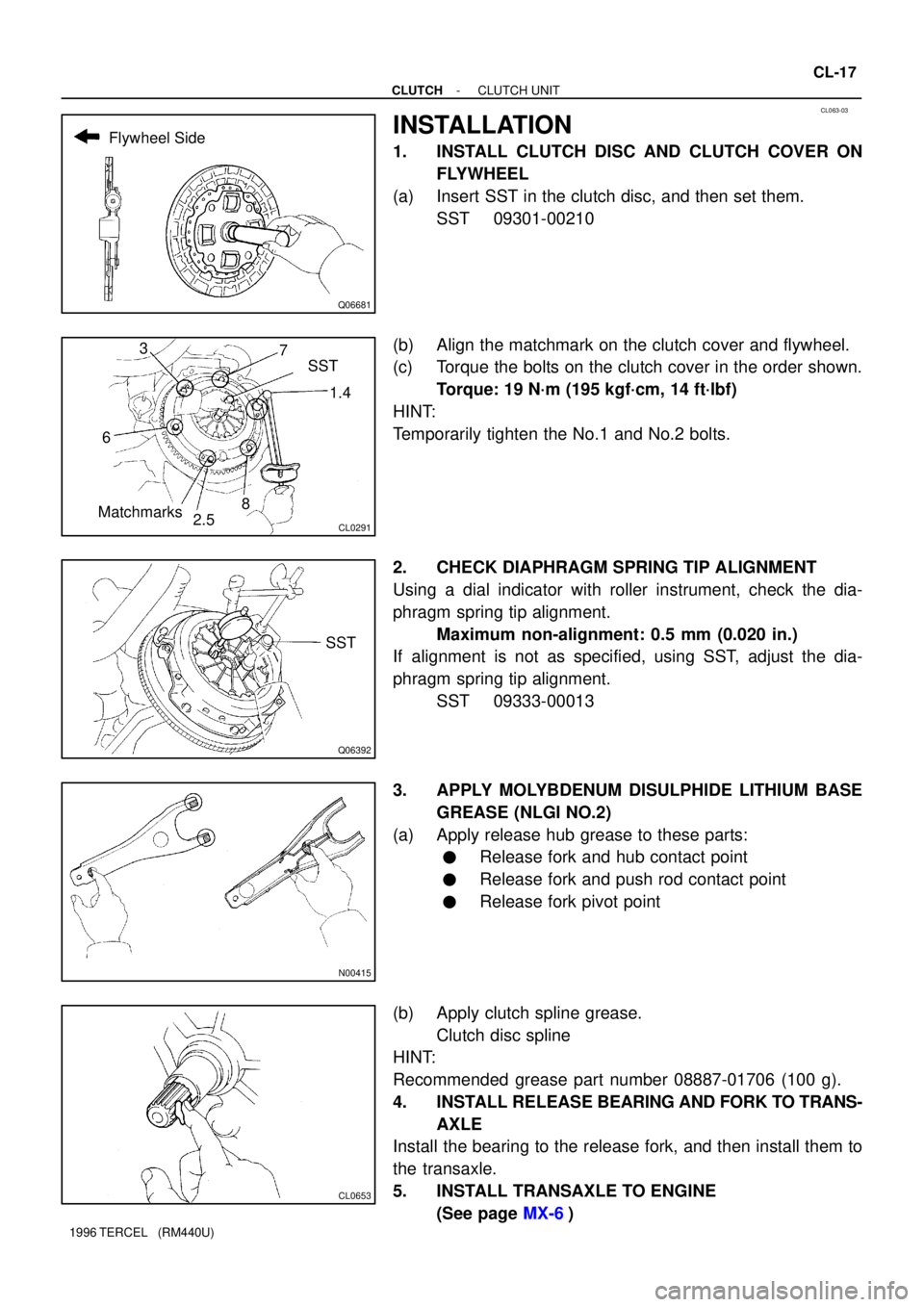
CL063-03
Q06681
Flywheel Side
CL0291
1.4
MatchmarksSST 7 3
6
2.58
Q06392
SST
N00415
CL0653
- CLUTCHCLUTCH UNIT
CL-17
1996 TERCEL (RM440U)
INSTALLATION
1. INSTALL CLUTCH DISC AND CLUTCH COVER ON
FLYWHEEL
(a) Insert SST in the clutch disc, and then set them.
SST 09301-00210
(b) Align the matchmark on the clutch cover and flywheel.
(c) Torque the bolts on the clutch cover in the order shown.
Torque: 19 N´m (195 kgf´cm, 14 ft´lbf)
HINT:
Temporarily tighten the No.1 and No.2 bolts.
2. CHECK DIAPHRAGM SPRING TIP ALIGNMENT
Using a dial indicator with roller instrument, check the dia-
phragm spring tip alignment.
Maximum non-alignment: 0.5 mm (0.020 in.)
If alignment is not as specified, using SST, adjust the dia-
phragm spring tip alignment.
SST 09333-00013
3. APPLY MOLYBDENUM DISULPHIDE LITHIUM BASE
GREASE (NLGI NO.2)
(a) Apply release hub grease to these parts:
�Release fork and hub contact point
�Release fork and push rod contact point
�Release fork pivot point
(b) Apply clutch spline grease.
Clutch disc spline
HINT:
Recommended grease part number 08887-01706 (100 g).
4. INSTALL RELEASE BEARING AND FORK TO TRANS-
AXLE
Install the bearing to the release fork, and then install them to
the transaxle.
5. INSTALL TRANSAXLE TO ENGINE
(See page MX-6)
Page 717 of 1202

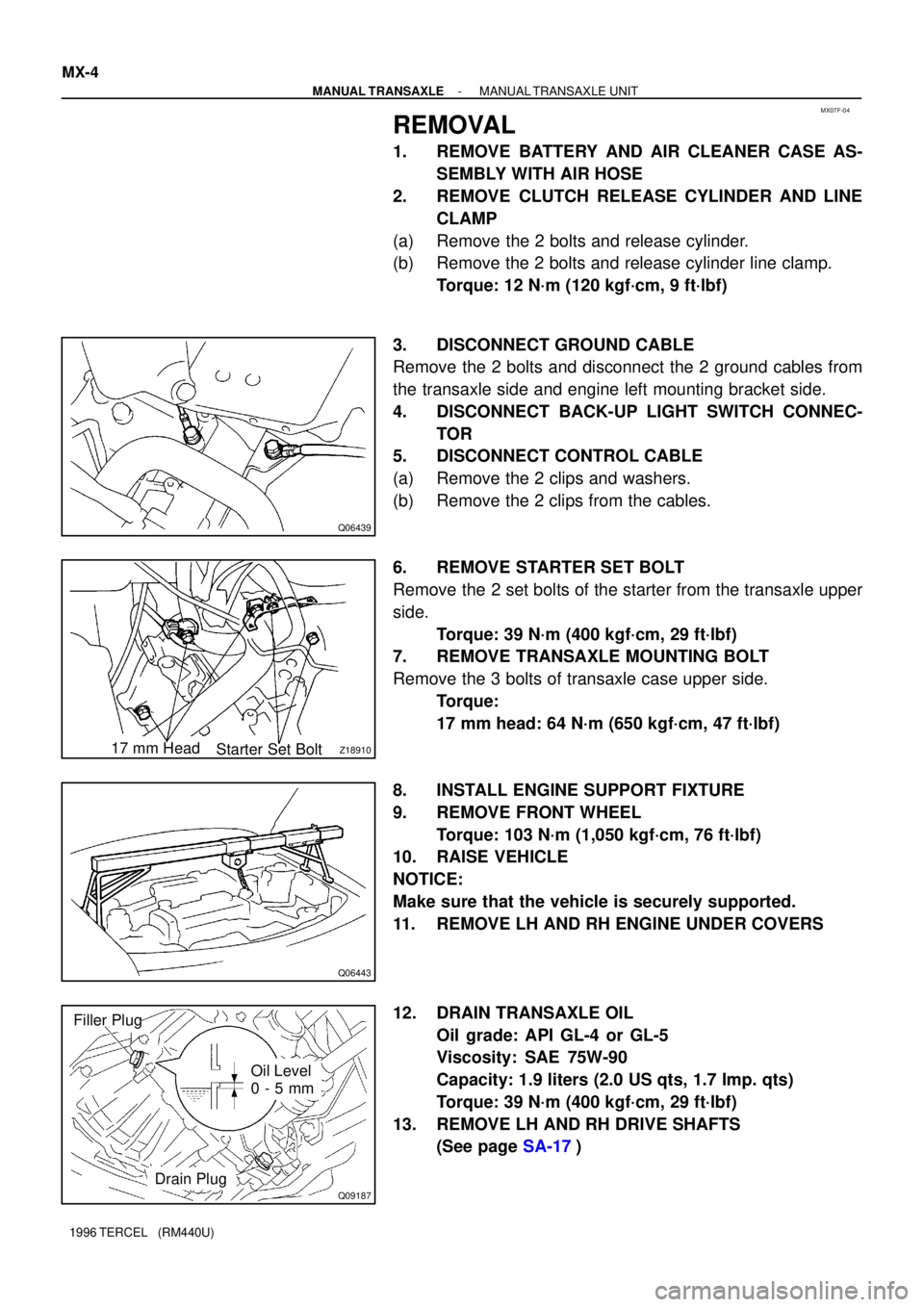
MX07F-04
Q06439
Z1891017 mm Head
Starter Set Bolt
Q06443
Q09187
Filler Plug
Oil Level
0 - 5 mm
Drain Plug MX-4
- MANUAL TRANSAXLEMANUAL TRANSAXLE UNIT
1996 TERCEL (RM440U)
REMOVAL
1. REMOVE BATTERY AND AIR CLEANER CASE AS-
SEMBLY WITH AIR HOSE
2. REMOVE CLUTCH RELEASE CYLINDER AND LINE
CLAMP
(a) Remove the 2 bolts and release cylinder.
(b) Remove the 2 bolts and release cylinder line clamp.
Torque: 12 N´m (120 kgf´cm, 9 ft´lbf)
3. DISCONNECT GROUND CABLE
Remove the 2 bolts and disconnect the 2 ground cables from
the transaxle side and engine left mounting bracket side.
4. DISCONNECT BACK-UP LIGHT SWITCH CONNEC-
TOR
5. DISCONNECT CONTROL CABLE
(a) Remove the 2 clips and washers.
(b) Remove the 2 clips from the cables.
6. REMOVE STARTER SET BOLT
Remove the 2 set bolts of the starter from the transaxle upper
side.
Torque: 39 N´m (400 kgf´cm, 29 ft´lbf)
7. REMOVE TRANSAXLE MOUNTING BOLT
Remove the 3 bolts of transaxle case upper side.
Torque:
17 mm head: 64 N´m (650 kgf´cm, 47 ft´lbf)
8. INSTALL ENGINE SUPPORT FIXTURE
9. REMOVE FRONT WHEEL
Torque: 103 N´m (1,050 kgf´cm, 76 ft´lbf)
10. RAISE VEHICLE
NOTICE:
Make sure that the vehicle is securely supported.
11. REMOVE LH AND RH ENGINE UNDER COVERS
12. DRAIN TRANSAXLE OIL
Oil grade: API GL-4 or GL-5
Viscosity: SAE 75W-90
Capacity: 1.9 liters (2.0 US qts, 1.7 Imp. qts)
Torque: 39 N´m (400 kgf´cm, 29 ft´lbf)
13. REMOVE LH AND RH DRIVE SHAFTS
(See page SA-17)