Page 758 of 1202
AUTOMATIC TRANSAXLE SYSTEM (A132L)
AX-5
1996 TERCEL (RM440U)
(2) Using an ohmmeter, check continuity between each
terminal shown below w")
AT8103
Neutral Basic Line
Groove
- AUTOMATIC TRANSAXLE (A132L)AUTOMATIC TRANSAXLE SYSTEM (A132L)
AX-5
1996 TERCEL (RM440U)
(2) Using an ohmmeter, check continuity between each
terminal shown below when the shift lever is put in
each position.
(h) Adjust the shift control cable.
(1) Remove the engine under cover.
(2) Loosen the nut on the control shaft lever.
(3) Push the control shaft lever fully toward the right
side of the vehicle.
(4) Return the lever 2 notches to the NEUTRAL posi-
tion.
(5) Set the shift lever to the N position.
(6) While holding the lever lightly toward the ºRº posi-
tion side, tighten the swivel nut.
(i) Adjust the park/neutral position switch.
If the engine will start with the shift selector in any position other
than the N or P position, adjustment is required.
(1) Loosen the park/neutral position switch bolts and
set the shift selector to the N position.
(2) Align the groove with neutral basic line.
(3) Hold the switch in the position and tighten the bolts.
Torque: 5.4 N´m (55 kgf´cm, 48 in.´lbf)
(j) Inspect the idle speed.
Idle speed:
750 ± 50 rpm (In the N position and A/C OFF)
3. MEASURE STALL TEST
The object of this test is to check the overall performance of the transaxle and the engine by measuring the
maximum engine speeds in the D and R positions.
NOTICE:
�Do the test at normal operating fluid temperature 50 - 80°C (122 - 176 °F).
�Do not continuously run this test longer than 5 seconds.
(1) Check the front and rear wheels.
(2) Connect the tachometer to the engine.
(3) Fully apply the parking brake.
Page 822 of 1202
F03984
R15511
�
�
- SUSPENSION AND AXLEFRONT WHEEL ALIGNMENT
SA-5
821 Author�: Date�:
1996 TERCEL (RM440U)
5. ADJUST CAMBER
NOTICE:
After the camber has been adjusted, inspect the toe-in.
(a) Remove the front wheels.
(b) Remove the 2 nuts on the lower side of the shock absorb-
er.
(c) Coat the threads of the nuts with engine oil.
(d) Temporarily install the 2 nuts.
(e) Adjust the camber by pushing or pulling the lower side of
the shock absorber in the direction in which the camber
adjustment is required.
Adjusting value: 0°06' - 0°30'
(f) Tighten the nuts.
Torque: 245 N´m (2,500 kgf´cm, 181 ft´lbf)
(g) Install the front wheels.
Torque: 103 N´m (1,050 kgf´cm, 76 ft´lbf)
(h) Check the camber.
Camber
Left-right error-0°20' ± 45'
45' (0.75°) or less
HINT:
�Try to adjust the camber to the center value.
�Adjusting value for the set bolts is 6' - 30' (0.1° - 0.5°).
Page 823 of 1202

F01195
Bolt
Adjusting
ValueSet Bolt
15'
30'Adjusting Bolt90105-15001 90105-15004 90105-15005 90105-15006
45'
1°00'
1°15'
1°30'121212121 Dot 2 Dots 3 Dots
W00533
W00533
SA-6
- SUSPENSION AND AXLEFRONT WHEEL ALIGNMENT
822 Author�: Date�:
1996 TERCEL (RM440U)
If the camber is not within the specification, using the table be-
low, estimate of how much additional camber adjustment will be
required, and select the camber adjusting bolt.
(i) Follow the above mentioned steps again. Between step
(b) and (c), exchange 1 or 2 selected bolts.
HINT:
When exchanging the 2 bolts, exchange 1 bolt for each time.
6. ADJUST TOE-IN
(a) Remove the boot clamps.
(b) Loosen the tie rod end lock nuts.
(c) Turn the left and right rack ends an equal amount to adjust
the toe-in.
Toe-in
(total)A + B: 0.1° ± 0.2°
C - D: 1 ± 2 mm (0.04 ± 0.08 in.)
HINT:
�Try to adjust the toe-in to the center value.
�Make sure that the lengths of the left and right rack ends
are the same.
Tie rod end length difference: 1.5 mm (0.059 in.) or
less
(d) Torque the tie rod end lock nuts.
Torque: 47 N´m (480 kgf´cm, 35 ft´lbf)
(e) Place the boots on the seat and install the clamps to them.
HINT:
Make sure that the boots are not twisted.
Page 827 of 1202

REMOVAL
1. REMOVE FRONT WHEEL
Torque: 103 N´m (1,050 kgf´cm, 76 ft´lbf)
2. w/ ABS
REMOVE BOLT AND ABS")
SA114-03
R11682
F03986
F03987
SA-10
- SUSPENSION AND AXLEFRONT AXLE HUB
1996 TERCEL (RM440U)
REMOVAL
1. REMOVE FRONT WHEEL
Torque: 103 N´m (1,050 kgf´cm, 76 ft´lbf)
2. w/ ABS
REMOVE BOLT AND ABS SPEED SENSOR
Torque: 7.8 N´m (80 kgf´cm, 69 in.´lbf)
3. REMOVE FRONT BRAKE CALIPER AND DISC
(a) Remove the 2 bolts and brake caliper from the steering
knuckle.
Torque: 88 N´m (900 kgf´cm, 65 in.´lbf)
(b) Support the brake caliper securely.
(c) Remove the disc.
4. CHECK BACKLASH IN BEARING SHAFT DIRECTION
Using a dial indicator, check the backlash near the center of the
axle hub, and check the backlash in the bearing shaft direction.
Maximum: 0.05 mm (0.0020 in.)
If the backlash exceeds the maximum, replace the bearing.
5. CHECK AXLE HUB DEVIATION
Using a dial indicator, check the deviation at the surface of the
axle hub outside the hub bolt.
Maximum: 0.05 mm (0.0020 in.)
If the deviation exceeds the maximum, replace the axle hub.
6. REMOVE DRIVE SHAFT LOCK NUT
(a) Install the brake disc and caliper.
(b) Remove the cotter pin and lock cap.
(c) With applying the brakes, remove the nut.
Torque: 216 N´m (2,200 kgf´cm, 159 ft´lbf)
(d) Remove the brake caliper and disc.
7. LOOSEN 2 NUTS ON LOWER SIDE OF SHOCK AB-
SORBER
Torque: 245 N´m (2,500 kgf´cm, 181 ft´lbf)
HINT:
�Do not remove the 2 bolts.
�Coat the nut's thread with engine oil.
Page 833 of 1202
SA118-03
N00187
SST
N00188
Washer SA-16
- SUSPENSION AND AXLEFRONT WHEEL HUB BOLT
832 Author�: Date�:
1996 TERCEL (RM440U)
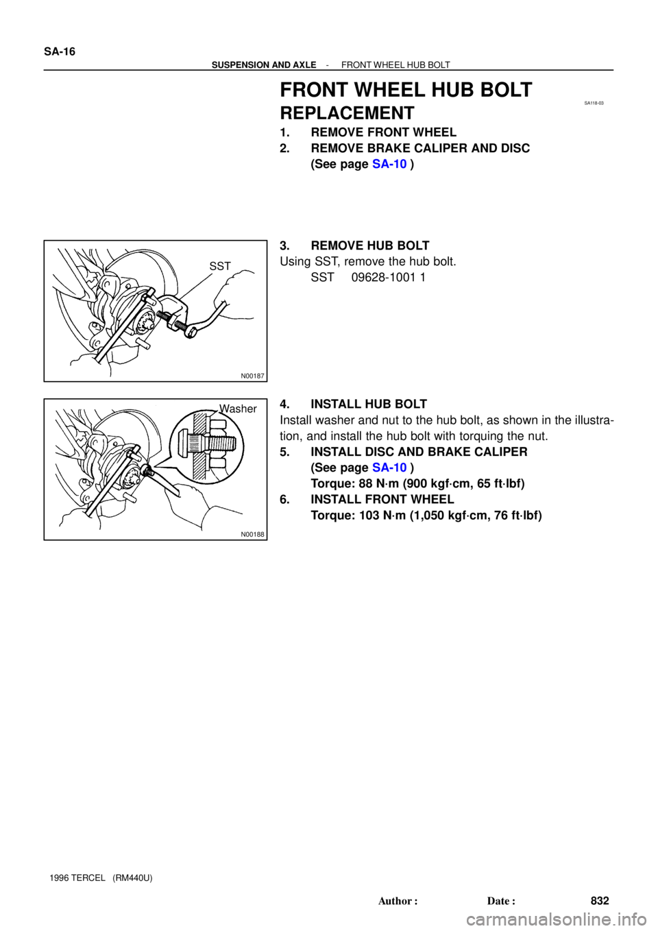
FRONT WHEEL HUB BOLT
REPLACEMENT
1. REMOVE FRONT WHEEL
2. REMOVE BRAKE CALIPER AND DISC
(See page SA-10)
3. REMOVE HUB BOLT
Using SST, remove the hub bolt.
SST 09628-1001 1
4. INSTALL HUB BOLT
Install washer and nut to the hub bolt, as shown in the illustra-
tion, and install the hub bolt with torquing the nut.
5. INSTALL DISC AND BRAKE CALIPER
(See page SA-10)
Torque: 88 N´m (900 kgf´cm, 65 ft´lbf)
6. INSTALL FRONT WHEEL
Torque: 103 N´m (1,050 kgf´cm, 76 ft´lbf)
Page 835 of 1202

REMOVAL
NOTICE:
�The hub bearing could be damaged if it is subjected
to the vehicle weight, such as when")
SA128-02
FA1535
SST
F03986
SA-18
- SUSPENSION AND AXLEFRONT DRIVE SHAFT
1996 TERCEL (RM440U)
REMOVAL
NOTICE:
�The hub bearing could be damaged if it is subjected
to the vehicle weight, such as when moving the ve-
hicle with the drive shaft removed. Therefore, if it is
absolutely necessary to place the vehicle weight on
the hub bearing, first support it with SST.
SST 09608-16042 (09608-02021, 09608-02041)
�w/ ABS:
After disconnecting the drive shaft from the axle hub,
work carefully so as not to damage the sensor rotor
serrations on the drive shaft.
1. REMOVE FRONT WHEEL
Torque: 103 N´m (1,050 kgf´cm, 76 ft´lbf)
2. M/T:
REMOVE LH ENGINE UNDER COVER
3. DRAIN TRANSAXLE OIL (M/T) OR ATF (A/T)
4. w/ ABS:
REMOVE BOLT AND ABS SPEED SENSOR
Torque: 7.8 N´m (80 kgf´cm, 69 in.´lbf)
5. REMOVE DRIVE SHAFT LOCK NUT
(a) Remove the cotter pin and lock cap.
(b) While applying the brakes, remove the nut.
Torque: 216 N´m (2,200 kgf´cm, 159 ft´lbf)
6. DISCONNECT TIE ROD END FROM STEERING
KNUCKLE (See page SA-10)
7. DISCONNECT LOWER BALL JOINT FROM LOWER
SUSPENSION ARM (See page SA-10)
8. DISCONNECT DRIVE SHAFT FROM AXLE HUB
NOTICE:
Be careful not to damage the drive shaft boot and inner oil
seal.
Page 842 of 1202
SA1W8-02
- SUSPENSION AND AXLEFRONT SHOCK ABSORBER
SA-25
1996 TERCEL (RM440U)
REMOVAL
1. REMOVE FRONT WHEEL
Torque: 103 N´m (1,050 kgf´cm, 76 ft´lbf)
2. REMOVE FLEXIBLE HOSE
Remove the bolt and disconnect the flexible hose from the shock absorber.
Torque: 29 N´m (300 kgf´cm, 22 ft´lbf)
3. w/ ABS:
DISCONNECT ABS SPEED SENSOR WIRE HARNESS
Remove the bolt and disconnect the ABS speed sensor wire harness from the shock absorber.
Torque: 5.4 N´m (55 kgf´cm, 48 in.´lbf)
4. DISCONNECT SHOCK ABSORBER FROM STEERING KNUCKLE
Remove the 2 nuts and bolts and disconnect the shock absorber from steering knuckle,
Torque: 245 N´m (2,500 kgf´cm, 181 ft´lbf)
HINT:
Coat the nut's threads with engine oil.
5. REMOVE SHOCK ABSORBER AND COIL SPRING
(a) Remove the 3/4 nuts on the upper side of the shock absorber.
Torque: 39 N´m (400 kgf´cm, 29 ft´lbf)
(b) Remove the shock absorber with the coil spring.
Page 849 of 1202
SA11H-04
R11688
Z14904
SA-32
- SUSPENSION AND AXLEFRONT LOWER SUSPENSION ARM
1996 TERCEL (RM440U)
REMOVAL
1. REMOVE FRONT WHEEL
Torque: 103 N´m (1,050 kgf´cm, 76 ft´lbf)
2. DISCONNECT LOWER SUSPENSION ARM FROM
LOWER BALL JOINT
Remove the 2 nuts and bolt.
Torque: 80 N´m (820 kgf´cm, 59 ft´lbf)
3. REMOVE LOWER SUSPENSION ARM
Remove the 3 bolts, lower suspension arm.
Torque:
A: 142 N´m (1,450 kgf´cm, 105 ft´lbf)
B: 74 N´m (750 kgf´cm, 55 ft´lbf)
HINT:
After stabilizing the suspension, torque the bolts.


REMOVAL
1. REMOVE FRONT WHEEL
Torque: 103 N´m (1,050 kgf´cm, 76 ft´lbf)
2. REMOVE FLEXIBLE HOSE
Remove the bolt and d")

REMOVAL
1. REMOVE FRONT WHEEL
Torque: 103 N´m (1,050 kgf´cm, 76 ft´lbf)
2. DISCONNECT LOWER SUSPE")