Page 661 of 1202
ST0MW-01
B05050
Magnetic Switch
Drive Level
Plate Washer
PlateStop Collar
Starter Housing
Snap Ring
Starter Clutch
Planetary GearPlate Carrier ShaftIntemal Gear
� Non-reusable partSnap Ring
Plate Washer
Center Beaning
Armature Plate Washer
� O-Ring Shock Absorber
Field Frame
(Field Coil)
End CoverBrush Holder� O-Ring
- STARTINGSTARTER (Planetary Type)
ST-15
660 Author�: Date�:
1996 TERCEL (RM440U)
STARTER (Planetary Type)
COMPONENTS
Page 667 of 1202

ST-21
1996 TERCEL (RM440U)
6. INSPECT CLUTCH AND GEAR
(a")
ST0661
Free
Lock
ST0667
P25604
Terminal C
Continuity Terminal 50
P25605
Continuity Terminal 50 Switch
Body
- STARTINGSTARTER (Planetary Type)
ST-21
1996 TERCEL (RM440U)
6. INSPECT CLUTCH AND GEAR
(a) Check the gear teeth on the planetary gear, internal gear
and starter clutch for wear or damage.
If the gear is damaged, replace it.
If the starter clutch teeth are damaged, replace the starter
clutch and also inspect the flywheel ring gear for wear or dam-
age.
(b) Check the starter clutch.
Rotate the clutch pinion gear clockwise and check that it
turns freely. Try to rotate the clutch pinion gear counter-
clockwise and check that it locks.
If necessary, replace the starter clutch.
7. INSPECT MAGNETIC SWITCH
(a) Check the plunger.
Push in the plunger and replace it. Check that it returns
quickly to its original position.
If necessary, replace the magnetic switch.
(b) Check the pull-in coil for open circuit.
Using an ohmmeter, check that there is continuity be-
tween terminals 50 and C.
If there is no continuity, replace the magnetic switch.
(c) Check the hold-in coil for open circuit.
Using an ohmmeter, check that there is continuity be-
tween terminal 50 and the switch body.
If there is no continuity, replace the magnetic switch.
Page 671 of 1202

ST-25
1996 TERCEL (RM440U)
REASSEMBLY
HINT:
U")
ST085-03
ST0646
Grease
ST0647
Hollow
Protrusion
ST0671
Planet Carrier Shaft
Plate Washer Shock Absorber
ST0672
ST0673
- STARTINGSTARTER (Planetary Type)
ST-25
1996 TERCEL (RM440U)
REASSEMBLY
HINT:
Use high temperature-resistant grease to lubricate the bear-
ings and sliding parts when assembling the starter.
1. INSTALL INTERNAL GEAR AND PLANET CARRIER
SHAFT
(a) Apply grease to the internal gear touching the shock ab-
sorber and planetary gears.
(b) Align the hollow of the internal gear with the protrusion in-
side the shock absorber.
(c) Insert and turn the internal gear so that it interlocks with
the shock absorber.
(d) Apply turbine oil to the center bearing.
(e) Apply grease to the plate washer, and install it to the plan-
et carrier shaft.
(f) Install the planet carrier shaft to the shock absorber.
(g) Using snap ring pliers, install the plate washer and snap
ring.
2. INSTALL STARTER CLUTCH
(a) Apply grease to the bushing and spline of the starter
clutch stop collar.
(b) Place the starter clutch and stop collar on the planet carri-
er shaft.
(c) Apply grease to the snap ring, and install it to the planet
carrier shaft groove.
(d) Using a vise, compress the snap ring.
Page 672 of 1202

1996 TERCEL (RM440U)
(e) Hold the starter clutch, tap the planet carrier shaft and
ins")
ST0674
Z07229
Protrusion
Cutout
ST1086
ST1089
Cutout
Protrusion
ST0656
ST-26
- STARTINGSTARTER (Planetary Type)
1996 TERCEL (RM440U)
(e) Hold the starter clutch, tap the planet carrier shaft and
install the stop collar onto the snap ring with a plastic-
faced hammer.
3. INSTALL PLANETARY GEARS
(a) Apply grease to the planetary gears and flange pin parts
of the planet carrier shaft.
(b) Install the plate washer and 3 planetary gears.
(c) Align the cutout of the plate with the protrusion inside the
shock absorber, and install the plate.
4. INSTALL DRIVE LEVER AND STARTER CLUTCH
WITH SHOCK ABSORBER
(a) Apply turbine oil to the bearing of the starter drive hous-
ing.
(b) Apply grease to the drive lever touching the starter pivot
part of the drive lever.
(c) Install the drive lever to the starter clutch.
(d) Align the protrusion of the shock absorber with the cutout
of the drive housing and install them.
5. PLACE ARMATURE INTO FIELD FRAME
6. INSTALL BRUSH HOLDER
(a) Place the brush holder in position on the armature.
(b) Using a screwdriver, hold the brush spring back, and con-
nect the brush into the brush holder. Connect the 4
brushes.
NOTICE:
Check that positive (+) lead wires are not grounded.
(c) Install a new O-ring to the groove of the field frame.
(d) Apply turbine oil to the bearing of the end cover.
Page 674 of 1202

1996 TERCEL (RM440U)
TEST
NOTICE:
These tests must be performed within 3 to")
ST086-01
P25503
Terminal C
Terminal 50
P25510
Disconnect
P25511
Disconnect
P25512
ST-28
- STARTINGSTARTER (Planetary Type)
1996 TERCEL (RM440U)
TEST
NOTICE:
These tests must be performed within 3 to 5 seconds to
avoid burning out the coil.
1. DO PULL-IN TEST
(a) Disconnect the field coil lead from terminal C.
(b) Connect the battery to the magnetic switch as shown.
Check that the clutch pinion gear moves outward.
If the clutch pinion gear does not move, replace the magnetic
switch.
2. DO HOLD-IN TEST
While connected as above with the clutch pinion gear out, dis-
connect the negative (-) lead from terminal C. Check that the
clutch pinion gear remains out.
If the clutch pinion gear returns inward, replace the magnetic
switch.
3. INSPECT CLUTCH PINION GEAR RETURN
Disconnect the negative (-) lead from the switch body. Check
that the clutch pinion gear returns inward.
If the clutch pinion gear does not return, replace the magnetic
switch.
4. INSPECT CLUTCH PINION GEAR CLEARANCE
(a) Connect the battery to the magnetic switch as shown.
Page 675 of 1202
ST1090
P25513
Terminal 30
Terminal 50
Ammeter
- STARTINGSTARTER (Planetary Type)
ST-29
1996 TERCEL (RM440U)
(b) Move the pinion gear toward the armature to remove
slack and measure the clearance between the pinion
gear end and stop collar.
Standard clearance: 1 - 5 mm (0.04 - 0.20 in.)
5. DO NO-LOAD PERFORMANCE TEST
(a) Connect the field coil lead to terminal C. Make sure the
lead is not grounded.
(b) Connect the battery and ammeter to the starter as shown.
(c) Check that the starter rotates smoothly and steadily with
the clutch pinion gear moving out. Check that the amme-
ter reads the specified current.
Specified current: At 11.5 V: 90 A or less
Page 715 of 1202
MX07D-03
MX-2
- MANUAL TRANSAXLETROUBLESHOOTING
714 Author�: Date�:
1996 TERCEL (RM440U)
TROUBLESHOOTING
PROBLEM SYMPTOMS TABLE
Use the table below to help you find the cause of the problem. The numbers indicate the priority of the likely
cause of the problem. Check each part in order. If necessary, replace these parts.
SymptomSuspect AreaSee page
Noise
15.Oil (Level low)
16.Oil (Wrong)
17.Gear (Worn or damaged)
18.Bearing (Worn or damaged)MX-4
MX-4
MX-7
MX-7
Oil leakage
1. Oil (Level too high)
2. Gasket (Damaged)
3. Oil seal (Worn or damaged)
4. O-Ring (Worn or damaged)MX-4
MX-7
MX-7
MX-7
Hard to shift or will not shift
1. Control cable (Faulty)
2. Synchronizer ring (Worn or damaged)
3. Shift key spring (Damaged)MX-40
MX-20
MX-27
MX-20
MX-27
Jumps out of gear
1. Locking ball spring (Damaged)
2. Shift fork (Worn)
3. Gear (Worn or damaged)
4. Bearing (Worn or damaged)MX-7
MX-7
MX-7
MX-7
Page 720 of 1202
MX07Z-04
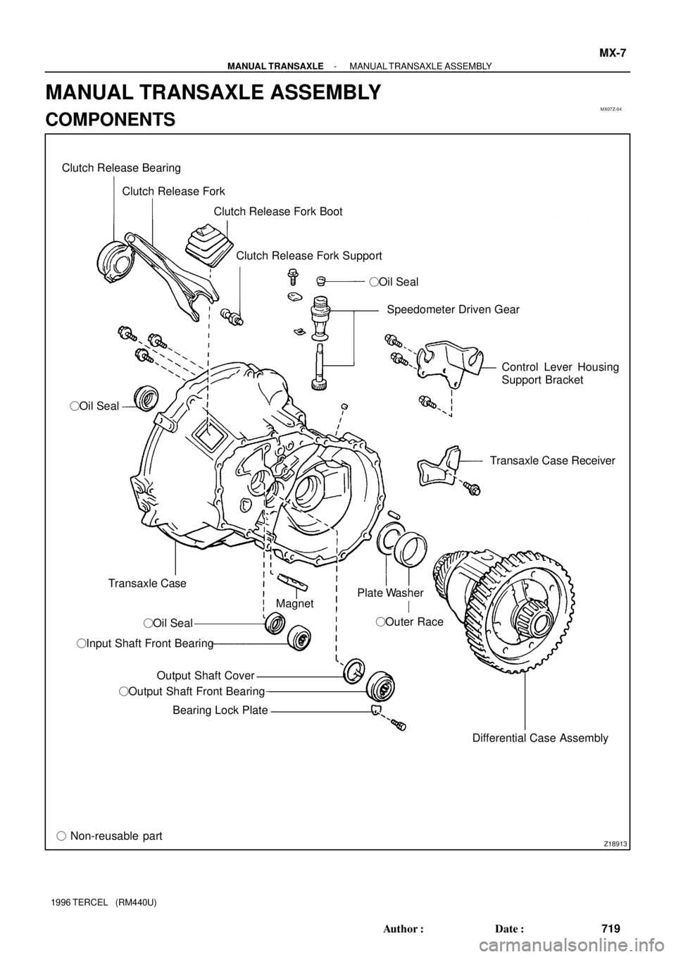
Z18913
Clutch Release Bearing
Clutch Release Fork
Clutch Release Fork Boot
Clutch Release Fork Support
�Oil Seal
�Oil Seal
Transaxle Case
�Oil Seal
�Input Shaft Front Bearing
Output Shaft Cover
�Output Shaft Front Bearing
Bearing Lock Plate
� Non-reusable partSpeedometer Driven Gear
Control Lever Housing
Support Bracket
Transaxle Case Receiver
Differential Case Assembly �Outer Race Magnet
Plate Washer
- MANUAL TRANSAXLEMANUAL TRANSAXLE ASSEMBLY
MX-7
719 Author�: Date�:
1996 TERCEL (RM440U)
MANUAL TRANSAXLE ASSEMBLY
COMPONENTS


ST-29
1996 TERCEL (RM440U)
(b) Move the pinion gear toward the armature to remove
slack and measure the clearance bet")