Page 671 of 1202
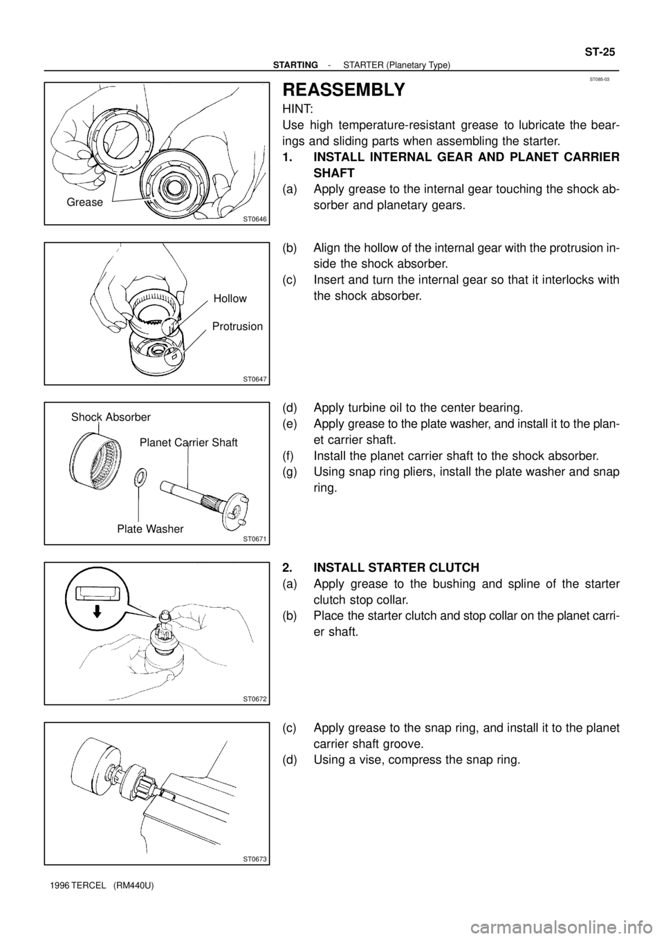
ST085-03
ST0646
Grease
ST0647
Hollow
Protrusion
ST0671
Planet Carrier Shaft
Plate Washer Shock Absorber
ST0672
ST0673
- STARTINGSTARTER (Planetary Type)
ST-25
1996 TERCEL (RM440U)
REASSEMBLY
HINT:
Use high temperature-resistant grease to lubricate the bear-
ings and sliding parts when assembling the starter.
1. INSTALL INTERNAL GEAR AND PLANET CARRIER
SHAFT
(a) Apply grease to the internal gear touching the shock ab-
sorber and planetary gears.
(b) Align the hollow of the internal gear with the protrusion in-
side the shock absorber.
(c) Insert and turn the internal gear so that it interlocks with
the shock absorber.
(d) Apply turbine oil to the center bearing.
(e) Apply grease to the plate washer, and install it to the plan-
et carrier shaft.
(f) Install the planet carrier shaft to the shock absorber.
(g) Using snap ring pliers, install the plate washer and snap
ring.
2. INSTALL STARTER CLUTCH
(a) Apply grease to the bushing and spline of the starter
clutch stop collar.
(b) Place the starter clutch and stop collar on the planet carri-
er shaft.
(c) Apply grease to the snap ring, and install it to the planet
carrier shaft groove.
(d) Using a vise, compress the snap ring.
Page 672 of 1202
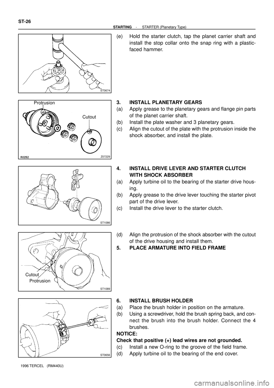
ST0674
Z07229
Protrusion
Cutout
ST1086
ST1089
Cutout
Protrusion
ST0656
ST-26
- STARTINGSTARTER (Planetary Type)
1996 TERCEL (RM440U)
(e) Hold the starter clutch, tap the planet carrier shaft and
install the stop collar onto the snap ring with a plastic-
faced hammer.
3. INSTALL PLANETARY GEARS
(a) Apply grease to the planetary gears and flange pin parts
of the planet carrier shaft.
(b) Install the plate washer and 3 planetary gears.
(c) Align the cutout of the plate with the protrusion inside the
shock absorber, and install the plate.
4. INSTALL DRIVE LEVER AND STARTER CLUTCH
WITH SHOCK ABSORBER
(a) Apply turbine oil to the bearing of the starter drive hous-
ing.
(b) Apply grease to the drive lever touching the starter pivot
part of the drive lever.
(c) Install the drive lever to the starter clutch.
(d) Align the protrusion of the shock absorber with the cutout
of the drive housing and install them.
5. PLACE ARMATURE INTO FIELD FRAME
6. INSTALL BRUSH HOLDER
(a) Place the brush holder in position on the armature.
(b) Using a screwdriver, hold the brush spring back, and con-
nect the brush into the brush holder. Connect the 4
brushes.
NOTICE:
Check that positive (+) lead wires are not grounded.
(c) Install a new O-ring to the groove of the field frame.
(d) Apply turbine oil to the bearing of the end cover.
Page 697 of 1202
CL05O-03
- CLUTCHTROUBLESHOOTING
CL-1
696 Author�: Date�:
1996 TERCEL (RM440U)
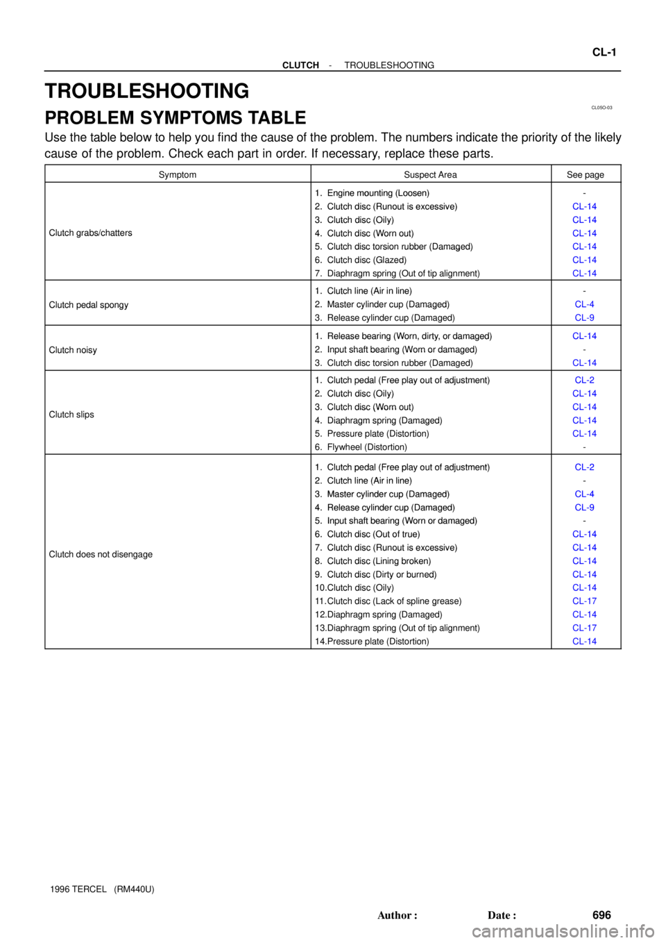
TROUBLESHOOTING
PROBLEM SYMPTOMS TABLE
Use the table below to help you find the cause of the problem. The numbers indicate the priority of the likely
cause of the problem. Check each part in order. If necessary, replace these parts.
SymptomSuspect AreaSee page
1. Engine mounting (Loosen)-1.Engine mounting (Loosen)
2. Clutch disc (Runout is excessive)
-
CL-14
2.Clutch disc (Runout is excessive)
3. Clutch disc (Oily)
CL-14
CL-14
Clutch grabs/chatters
3.Clutch disc (Oily)
4. Clutch disc (Worn out)
CL-14
CL-14Clutch grabs/chatters4.Clutch disc (Worn out)
5. Clutch disc torsion rubber (Damaged)
CL-14
CL-145.Clutch disc torsion rubber (Damaged)
6. Clutch disc (Glazed)
CL 14
CL-146.Clutch disc (Glazed)
7. Diaphragm spring (Out of tip alignment)
CL 14
CL-14
1. Clutch line (Air in line)-
Clutch pedal spongy
1.Clutch line (Air in line)
2. Master cylinder cup (Damaged)
-
CL-4
Clutch edal s ongy2.Master cylinder cu (Damaged)
3. Release cylinder cup (Damaged)
CL 4
CL-9
1. Release bearing (Worn, dirty, or damaged)CL-14
Clutch noisy
1.Release bearing (Worn, dirty, or damaged)
2. Input shaft bearing (Worn or damaged)
CL-14
-Clutch noisy2.In ut shaft bearing (Worn or damaged)
3. Clutch disc torsion rubber (Damaged)CL-14
1. Clutch pedal (Free play out of adjustment)CL-21.Clutch edal (Free lay out of adjustment)
2. Clutch disc (Oily)
CL-2
CL-14
Cl t h li
2.Clutch disc (Oily)
3. Clutch disc (Worn out)
CL-14
CL-14Clutch slips3.Clutch disc (Worn out)
4. Diaphragm spring (Damaged)
CL 14
CL-144.Dia hragm s ring (Damaged)
5. Pressure plate (Distortion)
CL 14
CL-145. Pressure late (Distortion)
6. Flywheel (Distortion)
CL 14
-
1 Clutchpedal (Freeplay out of adjustment)CL-21.Clutch pedal (Free play out of adjustment)
2 Clutch line (Air in line)CL-2
-2.Clutch line (Air in line)
3 Master cylinder cu
p(Damaged)
-
CL-43.Master cylinder cup (Damaged)
4. Release cylinder cu
p(Damaged)
CL-4
CL
-94.Release cylinder cup (Damaged)
5
. Input shaft bearing (Worn or damaged)
CL-9
-5.In ut shaft bearing (Worn or damaged)
6. Clutch disc (Out of true)
-
CL-14
Cl t h d t di
6.Clutch disc (Out of true)
7. Clutch disc (Runout is excessive)
CL-14
CL-14Clutch does not disengage7.Clutch disc (Runout is excessive)
8. Clutch disc (Lining broken)
CL-14
CL-148.Clutch disc (Lining broken)
9. Clutch disc (Dirty or burned)
CL-14
CL-149.Clutch disc (Dirty or burned)
10.Clutch disc (Oily)
CL 14
CL-1410.Clutch disc (Oily)
11. Clutch disc (Lack of spline grease)
CL 14
CL-1711. Clutch disc (Lack of s line grease)
12.Diaphragm spring (Damaged)
CL 17
CL-14gg(g)
13.Diaphragm spring (Out of tip alignment)CL-17gg( g)
14.Pressure plate (Distortion)CL-14
Page 720 of 1202
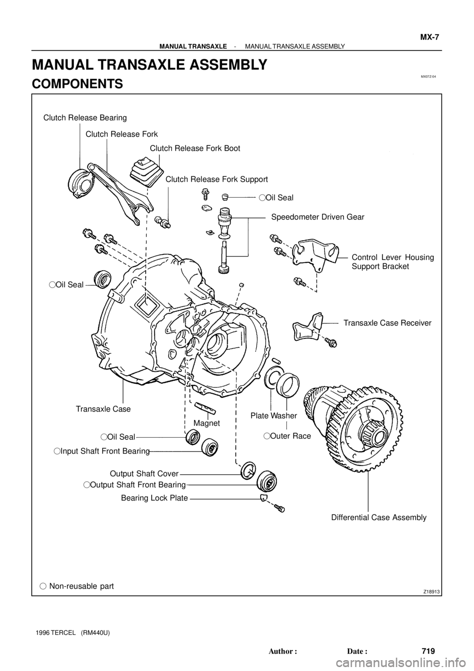
MX07Z-04
Z18913
Clutch Release Bearing
Clutch Release Fork
Clutch Release Fork Boot
Clutch Release Fork Support
�Oil Seal
�Oil Seal
Transaxle Case
�Oil Seal
�Input Shaft Front Bearing
Output Shaft Cover
�Output Shaft Front Bearing
Bearing Lock Plate
� Non-reusable partSpeedometer Driven Gear
Control Lever Housing
Support Bracket
Transaxle Case Receiver
Differential Case Assembly �Outer Race Magnet
Plate Washer
- MANUAL TRANSAXLEMANUAL TRANSAXLE ASSEMBLY
MX-7
719 Author�: Date�:
1996 TERCEL (RM440U)
MANUAL TRANSAXLE ASSEMBLY
COMPONENTS
Page 783 of 1202
AT0952
SST
AX0RT-01
AT0953
SST
AT3306
Hold
TurnLock
Free
AT2821
AT2820
AX-30
- AUTOMATIC TRANSAXLE (A132L)TORQUE CONVERTER CLUTCH AND DRIVE PLATE
782 Author�: Date�:
1996 TERCEL (RM440U)
TORQUE CONVERTER CLUTCH
AND DRIVE PLATE
INSPECTION
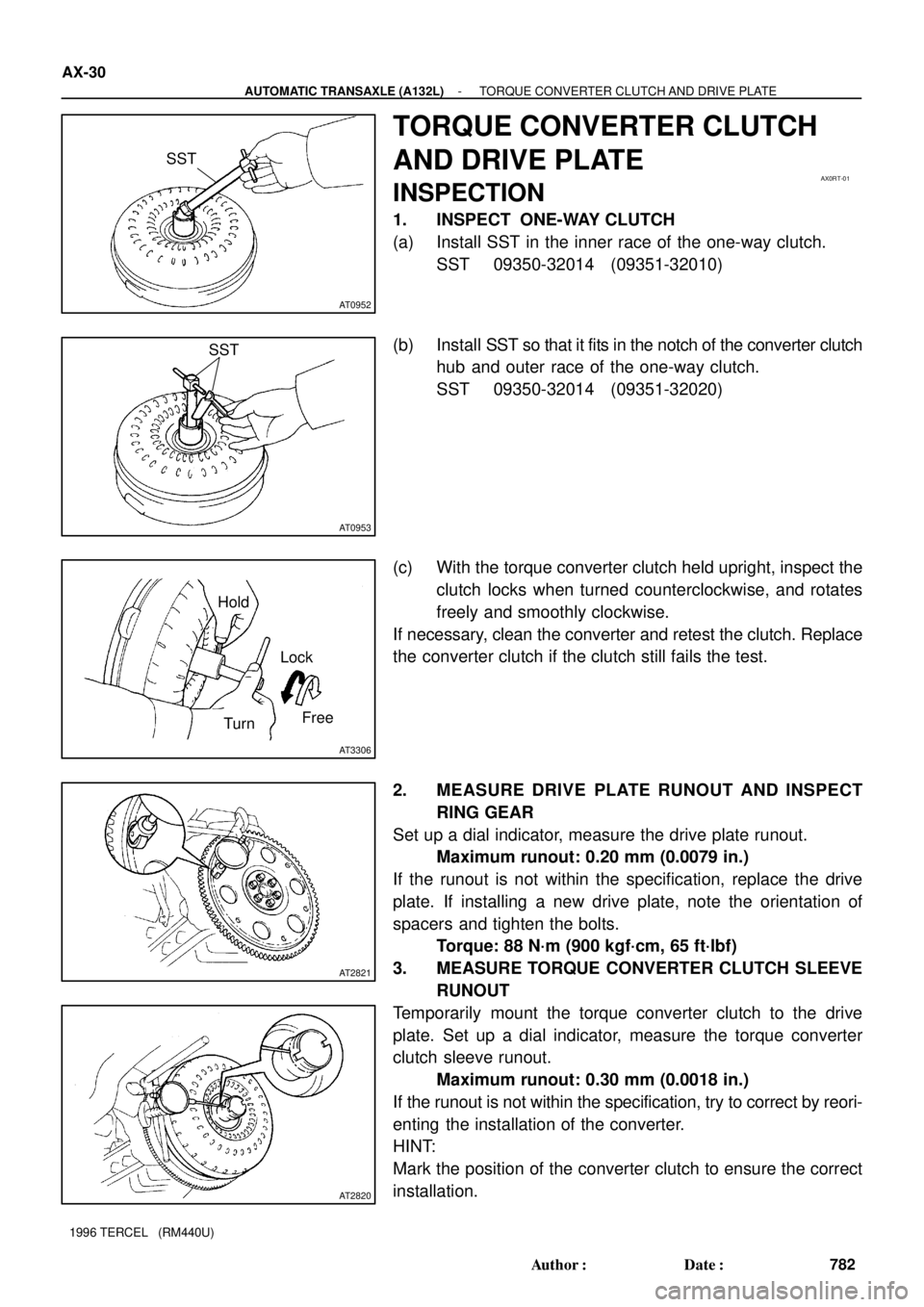
1. INSPECT ONE-WAY CLUTCH
(a) Install SST in the inner race of the one-way clutch.
SST 09350-32014 (09351-32010)
(b) Install SST so that it fits in the notch of the converter clutch
hub and outer race of the one-way clutch.
SST 09350-32014 (09351-32020)
(c) With the torque converter clutch held upright, inspect the
clutch locks when turned counterclockwise, and rotates
freely and smoothly clockwise.
If necessary, clean the converter and retest the clutch. Replace
the converter clutch if the clutch still fails the test.
2. MEASURE DRIVE PLATE RUNOUT AND INSPECT
RING GEAR
Set up a dial indicator, measure the drive plate runout.
Maximum runout: 0.20 mm (0.0079 in.)
If the runout is not within the specification, replace the drive
plate. If installing a new drive plate, note the orientation of
spacers and tighten the bolts.
Torque: 88 N´m (900 kgf´cm, 65 ft´lbf)
3. MEASURE TORQUE CONVERTER CLUTCH SLEEVE
RUNOUT
Temporarily mount the torque converter clutch to the drive
plate. Set up a dial indicator, measure the torque converter
clutch sleeve runout.
Maximum runout: 0.30 mm (0.0018 in.)
If the runout is not within the specification, try to correct by reori-
enting the installation of the converter.
HINT:
Mark the position of the converter clutch to ensure the correct
installation.
Page 817 of 1202
AT0952
SST
AX0S7-01
AT0953
AT3306
Hold
TurnLock
Free
AT2821
AT2820
AX-34
- AUTOMATIC TRANSAXLE (A242L)TORQUE CONVERTER CLUTCH AND DRIVE PLATE
816 Author�: Date�:
1996 TERCEL (RM440U)
TORQUE CONVERTER CLUTCH
AND DRIVE PLATE
INSPECTION
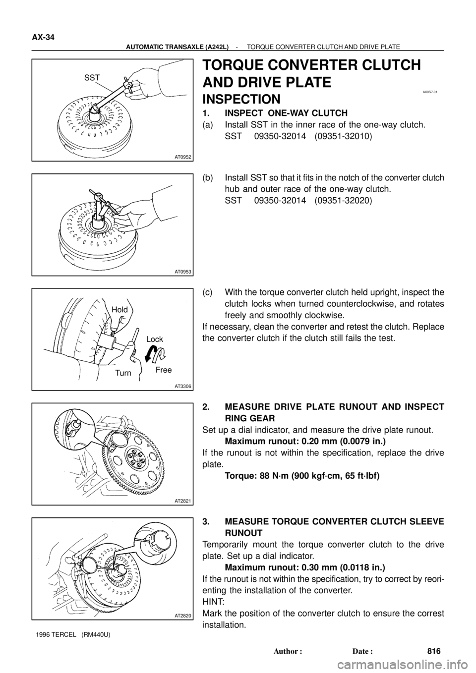
1. INSPECT ONE-WAY CLUTCH
(a) Install SST in the inner race of the one-way clutch.
SST 09350-32014 (09351-32010)
(b) Install SST so that it fits in the notch of the converter clutch
hub and outer race of the one-way clutch.
SST 09350-32014 (09351-32020)
(c) With the torque converter clutch held upright, inspect the
clutch locks when turned counterclockwise, and rotates
freely and smoothly clockwise.
If necessary, clean the converter and retest the clutch. Replace
the converter clutch if the clutch still fails the test.
2. MEASURE DRIVE PLATE RUNOUT AND INSPECT
RING GEAR
Set up a dial indicator, and measure the drive plate runout.
Maximum runout: 0.20 mm (0.0079 in.)
If the runout is not within the specification, replace the drive
plate.
Torque: 88 N´m (900 kgf´cm, 65 ft´lbf)
3. MEASURE TORQUE CONVERTER CLUTCH SLEEVE
RUNOUT
Temporarily mount the torque converter clutch to the drive
plate. Set up a dial indicator.
Maximum runout: 0.30 mm (0.0118 in.)
If the runout is not within the specification, try to correct by reori-
enting the installation of the converter.
HINT:
Mark the position of the converter clutch to ensure the correst
installation.
Page 1169 of 1202
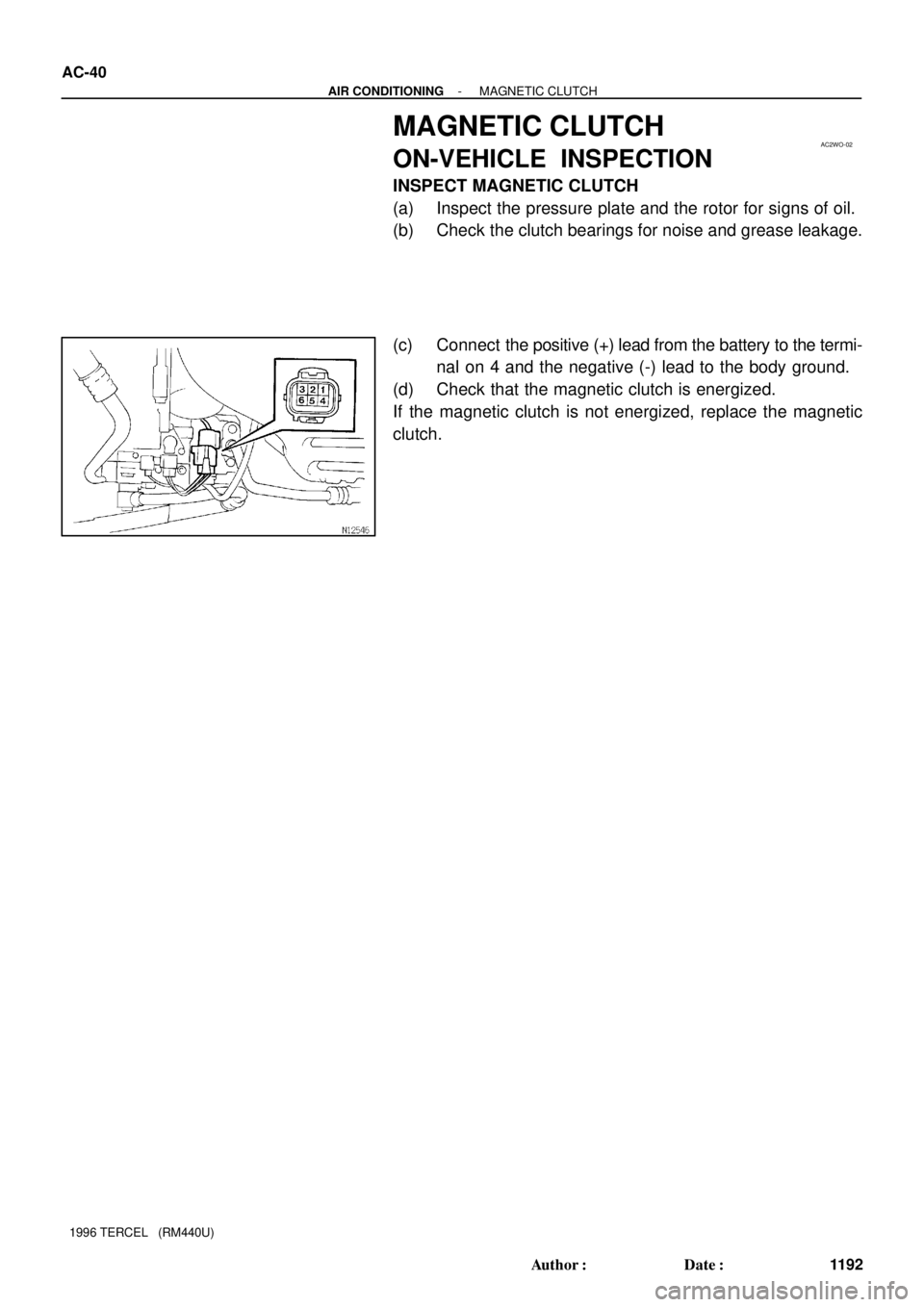
AC2WO-02
AC-40
- AIR CONDITIONINGMAGNETIC CLUTCH
1192 Author�: Date�:
1996 TERCEL (RM440U)
MAGNETIC CLUTCH
ON-VEHICLE INSPECTION
INSPECT MAGNETIC CLUTCH
(a) Inspect the pressure plate and the rotor for signs of oil.
(b) Check the clutch bearings for noise and grease leakage.
(c) Connect the positive (+) lead from the battery to the termi-
nal on 4 and the negative (-) lead to the body ground.
(d) Check that the magnetic clutch is energized.
If the magnetic clutch is not energized, replace the magnetic
clutch.
Page 1170 of 1202
AC2WP-02
N12676
Pressure Plate
� Snap RingCompressor
Stator Rotor
� Snap Ring
� Non-reusable part
Shim
- AIR CONDITIONINGMAGNETIC CLUTCH
AC-41
1996 TERCEL (RM440U)
COMPONENTS