Page 695 of 1202
Z10245
Type A
Z14809
Type B CH-18
- CHARGINGGENERATOR
1996 TERCEL (RM440U)
8. INSTALL REAR END COVER
(a) Type A:
Install the end cover with the 3 nuts.
Torque: 4.4 N´m (45 kgf´cm, 40 in.´lbf)
(b) Type B:
Install the end cover with the 3 bolts.
Torque: 4.4 N´m (45 kgf´cm, 40 in.´lbf)
(c) Install the terminal insulator with the nut.
Torque: 4.1 N´m (42 kgf´cm, 36 in.´lbf)
9. CHECK THAT ROTOR ROTATES SMOOTHLY
Page 701 of 1202
CL05R-01
Q06660
SST
- CLUTCHCLUTCH MASTER CYLINDER
CL-5
1996 TERCEL (RM440U)
REMOVAL
1. DRAW OUT FLUID WITH SYRINGE
2. DISCONNECT CLUTCH LINE
Using SST, disconnect the line. Use a container to catch the
fluid.
SST 09023-00100
Torque: 15 N´m (155 kgf´cm, 11 ft´lbf)
3. REMOVE CLIP AND CLEVIS PIN
4. REMOVE 2 MOUNTING NUTS AND PULL OUT MAS-
TER CYLINDER
Torque: 12 N´m (120 kgf´cm, 9 ft´lbf)
Page 706 of 1202
CL05W-01
Q06706SST CL-10
- CLUTCHCLUTCH RELEASE CYLINDER
1996 TERCEL (RM440U)
REMOVAL
1. DISCONNECT CLUTCH LINE
Using SST, disconnect the line. Use a container to catch the
fluid.
SST 09023-00100
Torque: 15 N´m (155 kgf´cm, 11 ft´lbf)
2. REMOVE 2 BOLTS AND PULL OUT RELEASE CYL-
INDER
Torque: 12 N´m (120 kgf´cm, 9 ft´lbf)
Page 713 of 1202

CL063-03
Q06681
Flywheel Side
CL0291
1.4
MatchmarksSST 7 3
6
2.58
Q06392
SST
N00415
CL0653
- CLUTCHCLUTCH UNIT
CL-17
1996 TERCEL (RM440U)
INSTALLATION
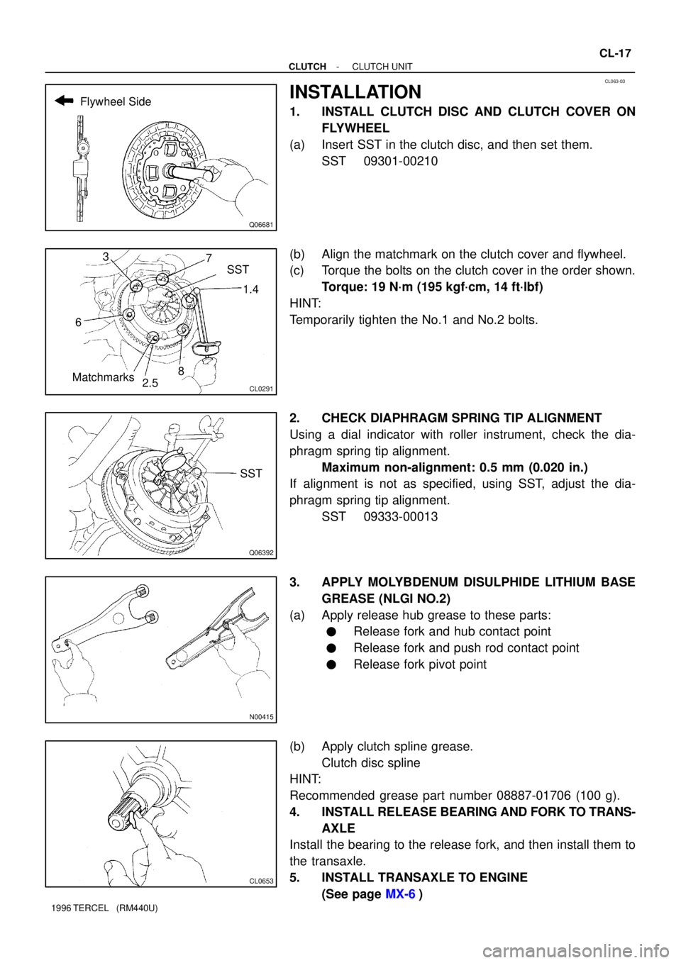
1. INSTALL CLUTCH DISC AND CLUTCH COVER ON
FLYWHEEL
(a) Insert SST in the clutch disc, and then set them.
SST 09301-00210
(b) Align the matchmark on the clutch cover and flywheel.
(c) Torque the bolts on the clutch cover in the order shown.
Torque: 19 N´m (195 kgf´cm, 14 ft´lbf)
HINT:
Temporarily tighten the No.1 and No.2 bolts.
2. CHECK DIAPHRAGM SPRING TIP ALIGNMENT
Using a dial indicator with roller instrument, check the dia-
phragm spring tip alignment.
Maximum non-alignment: 0.5 mm (0.020 in.)
If alignment is not as specified, using SST, adjust the dia-
phragm spring tip alignment.
SST 09333-00013
3. APPLY MOLYBDENUM DISULPHIDE LITHIUM BASE
GREASE (NLGI NO.2)
(a) Apply release hub grease to these parts:
�Release fork and hub contact point
�Release fork and push rod contact point
�Release fork pivot point
(b) Apply clutch spline grease.
Clutch disc spline
HINT:
Recommended grease part number 08887-01706 (100 g).
4. INSTALL RELEASE BEARING AND FORK TO TRANS-
AXLE
Install the bearing to the release fork, and then install them to
the transaxle.
5. INSTALL TRANSAXLE TO ENGINE
(See page MX-6)
Page 717 of 1202

MX07F-04
Q06439
Z1891017 mm Head
Starter Set Bolt
Q06443
Q09187
Filler Plug
Oil Level
0 - 5 mm
Drain Plug MX-4
- MANUAL TRANSAXLEMANUAL TRANSAXLE UNIT
1996 TERCEL (RM440U)
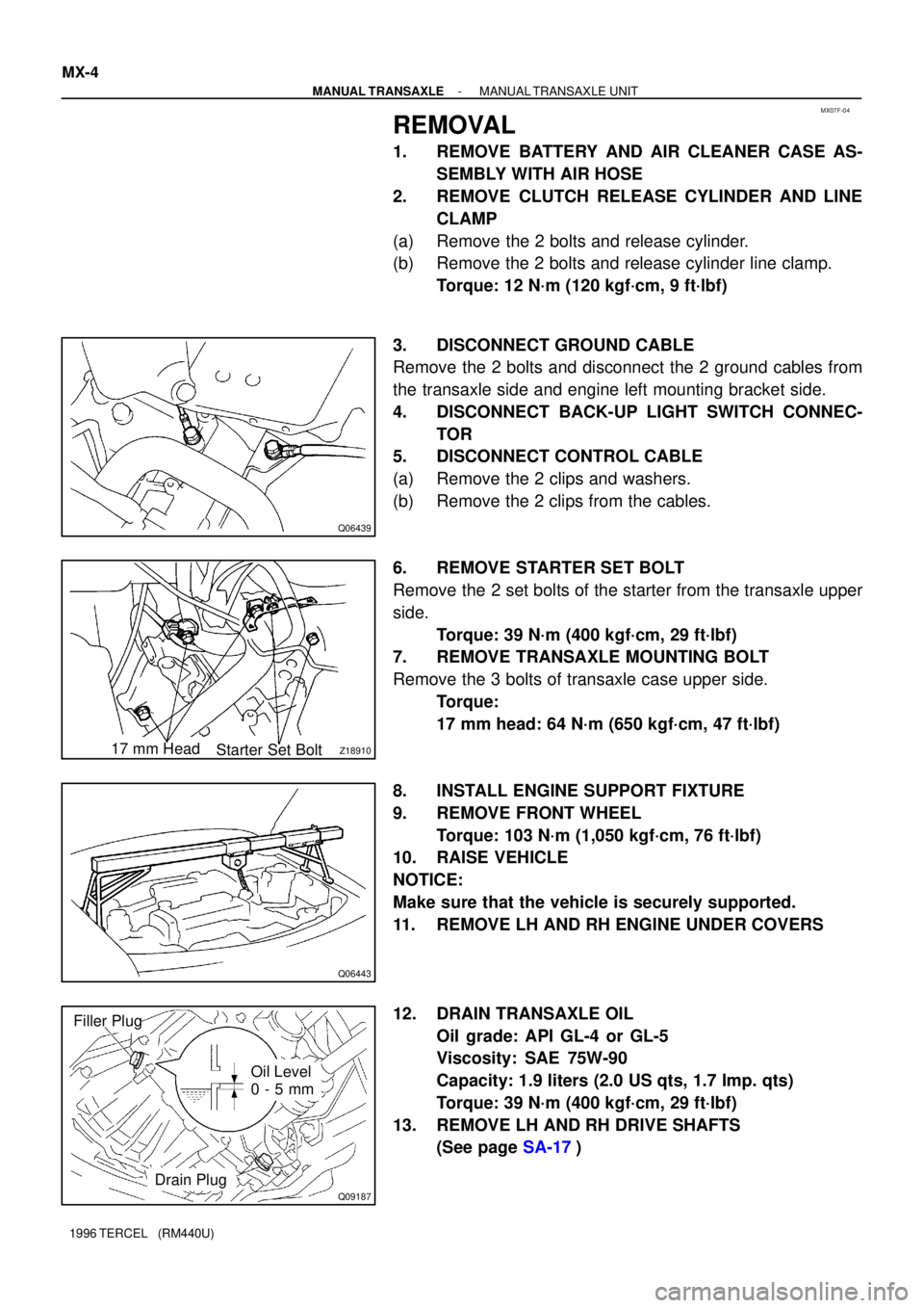
REMOVAL
1. REMOVE BATTERY AND AIR CLEANER CASE AS-
SEMBLY WITH AIR HOSE
2. REMOVE CLUTCH RELEASE CYLINDER AND LINE
CLAMP
(a) Remove the 2 bolts and release cylinder.
(b) Remove the 2 bolts and release cylinder line clamp.
Torque: 12 N´m (120 kgf´cm, 9 ft´lbf)
3. DISCONNECT GROUND CABLE
Remove the 2 bolts and disconnect the 2 ground cables from
the transaxle side and engine left mounting bracket side.
4. DISCONNECT BACK-UP LIGHT SWITCH CONNEC-
TOR
5. DISCONNECT CONTROL CABLE
(a) Remove the 2 clips and washers.
(b) Remove the 2 clips from the cables.
6. REMOVE STARTER SET BOLT
Remove the 2 set bolts of the starter from the transaxle upper
side.
Torque: 39 N´m (400 kgf´cm, 29 ft´lbf)
7. REMOVE TRANSAXLE MOUNTING BOLT
Remove the 3 bolts of transaxle case upper side.
Torque:
17 mm head: 64 N´m (650 kgf´cm, 47 ft´lbf)
8. INSTALL ENGINE SUPPORT FIXTURE
9. REMOVE FRONT WHEEL
Torque: 103 N´m (1,050 kgf´cm, 76 ft´lbf)
10. RAISE VEHICLE
NOTICE:
Make sure that the vehicle is securely supported.
11. REMOVE LH AND RH ENGINE UNDER COVERS
12. DRAIN TRANSAXLE OIL
Oil grade: API GL-4 or GL-5
Viscosity: SAE 75W-90
Capacity: 1.9 liters (2.0 US qts, 1.7 Imp. qts)
Torque: 39 N´m (400 kgf´cm, 29 ft´lbf)
13. REMOVE LH AND RH DRIVE SHAFTS
(See page SA-17)
Page 718 of 1202

Q06552
Q08461
AB
C
CC
A
Q06446
Q08159
- MANUAL TRANSAXLEMANUAL TRANSAXLE UNIT
MX-5
1996 TERCEL (RM440U)
14. REMOVE FRONT EXHAUST PIPE
(a) Disconnect the oxygen sensor.
(b) Remove the 2 bolts, springs and gasket.
Torque: 62 N´m (630 kgf´cm, 46 ft´lbf)
(c) Remove the bolt, clamp and gasket.
Torque: 19 N´m (190 kgf´cm, 14 ft´lbf)
(d) Disconnect the 2 rings and remove the exhaust front pipe.
15. REMOVE STARTER
Disconnect the connector and wire and remove the starter.
16. DISCONNECT SPEEDOMETER CABLE
17. REMOVE ENGINE REAR MOUNTING INSULATOR
Remove the 6 bolts and insulator.
Torque:
Bolt A: 78 N´m (800 kgf´cm, 58 ft´lbf)
Bolt B: 64 N´m (650 kgf´cm, 47 ft´lbf)
Bolt C: 90 N´m (920 kgf´cm, 67 ft´lbf)
18. DISCONNECT ENGINE LEFT MOUNTING BRACKET
FROM ENGINE LEFT MOUNTING INSULATOR
Remove the 2 bolts.
Torque: 48 N´m (490 kgf´cm, 36 ft´lbf)
19. JACK UP TRANSAXLE SLIGHTLY
Using a transmission jack, support the transaxle.
20. REMOVE TRANSAXLE LOWER SIDE MOUNTING
BOLT
Remove the 4 bolts.
Torque:
14 mm head: 46 N´m (470 kgf´cm, 34 ft´lbf)
10 mm head: 7.4 N´m (75 kgf´cm, 65 in.´lbf)
21. REMOVE TRANSAXLE
Lower the engine left side and remove the transaxle from the
engine.
HINT:
�Align the input shaft with the clutch disc and install the
transaxle to the engine.
�Install and torque the 7 bolts.
Torque:
Upper side mounting bolts: (See step 7)
Lower side mounting bolts: (See step 20)
Page 723 of 1202

MX0B1-02
Q07828
FIPG
N00038
N00039
MX-10
- MANUAL TRANSAXLEMANUAL TRANSAXLE ASSEMBLY
1996 TERCEL (RM440U)
DISASSEMBLY
1. REMOVE RELEASE FORK AND BEARING
HINT:
Apply molybdenum disulphide lithium base grease
(See page CL-17).
2. REMOVE SPEEDOMETER DRIVEN GEAR
Remove the driven gear lock plate set bolt and driven gear.
Torque: 11 N´m (115 kgf´cm, 8 ft´lbf)
3. REMOVE BACK-UP LIGHT SWITCH
Torque: 40 N´m (410 kgf´cm, 30 ft´lbf)
4. REMOVE CONTROL LEVER HOUSING SUPPORT
BRACKET
Remove the 3 bolts and bracket.
Torque: 11 N´m (115 kgf´cm, 8 ft´lbf)
5. REMOVE SELECTING BELLCRANK ASSEMBLY
Remove the 2 bolts and selecting bellcrank assembly.
Torque: 25 N´m (250 kgf´cm, 18 ft´lbf)
6. REMOVE TRANSMISSION CASE COVER
(a) Remove the 9 bolts.
Torque: 18 N´m (185 kgf´cm, 13 ft´lbf)
(b) Carefully tap the projection of the transmission case cov-
er with a brass bar and hammer and remove the cover.
FIPG:
Part No. 08826-00090, THREE BOND 1281 or equiva-
lent
7. C151:
INSPECT 5TH GEAR THRUST CLEARANCE
Using a dial indicator, measure the thrust clearance.
Standard clearance:
0.10 - 0.57 mm (0.0039 - 0.0224 in.)
Maximum clearance: 0.65 mm (0.0256 in.)
8. C151:
INSPECT 5TH GEAR RADIAL CLEARANCE
Using a dial indicator, measure the radial clearance.
Standard clearance:
0.015 - 0.058 mm (0.0006 - 0.0023 in.)
Maximum clearance: 0.070 mm (0.0028 in.)
If the clearance exceeds the maximum, replace the gear,
needle roller bearing or shaft.
Page 724 of 1202

Q06523
Lock Bolt
Q06512
Q06531
SST
- MANUAL TRANSAXLEMANUAL TRANSAXLE ASSEMBLY
MX-1 1
1996 TERCEL (RM440U)
9. REMOVE SHIFT AND SELECT LEVER SHAFT AS-
SEMBLY
(a) Remove the lock bolt.
Torque: 29 N´m (300 kgf´cm, 22 ft´lbf)
(b) Remove the 4 bolts and pull out the shift and select lever
shaft assembly with the gasket.
Sealant:
Part No.08833-00080, THREE BOND 1344, LOCTITE
242 or equivalent
Torque: 20 N´m (200 kgf´cm, 14 ft´lbf)
10. REMOVE LOCK NUT
(a) Engage the gear double meshing.
(b) Using a hammer and chisel, loosen the staked part of the
nut.
(c) Remove the lock nut.
Torque: 118 N´m (1,200 kgf´cm, 87 ft´lbf)
(d) C141:
Remove the spacer.
(e) Disengage the gear double meshing.
11. C151:
REMOVE NO.3 HUB SLEEVE AND NO.3 SHIFT FORK
(a) Remove the bolt from the No.3 shift fork.
Torque: 16 N´m (160 kgf´cm, 12 ft´lbf)
(b) Remove the No.3 hub sleeve and shift fork.
12. C151:
REMOVE NO.3 CLUTCH HUB AND 5TH GEAR
(a) Using 2 screwdrivers and a hammer, tap out the snap
ring.
HINT:
Select a snap ring that will allow minimum axial play.
MarkThickness mm (in.)MarkThickness mm (in.)
A2.25 (0.0886)E2.49 (0.0980)
B2.31 (0.0909)F2.55 (0.1004)
C2.37 (0.0933)G2.61 (0.1028)
D2.43 (0.0957)--
(b) Using SST, remove the 5th gear, No.3 clutch hub, syn-
chronizer ring, needle roller bearings and spacer.
SST 09950-40010