Page 1594 of 2062
Downloaded from www.Manualslib.com manuals search engine SA0HS−01
R04505
R05271
SA−124
− SUSPENSION AND AXLEFRONT STABILIZER BAR (2WD)
1996 TOYOTA T100 (RM449U)
REMOVAL
1. REMOVE FRONT WHEEL
Torque: 103 N·m (1,050 kgf·cm, 76 ft·lbf)
2. REMOVE STABILIZER BAR
(a) Remove the nut, 3 retainers, 2 cushions and stabilizer bar
from the lower suspension arm.
Torque: 13 N·m (130 kgf·cm, 9 ft·lbf)
(b) Remove the nut, 2 cushions, 2 retainers and disconnect
the stabilizer bar.
Torque: 13 N·m (130 kgf·cm, 9 ft·lbf)
(c) Employ the same manner described above to the other
side.
(d) Remove the 4 bolts, stabilizer bar brackets, bushings and
remove the stabilizer bar.
Torque: 30 N·m (306 kgf·cm, 22 ft·lbf)
Page 1597 of 2062
Downloaded from www.Manualslib.com manuals search engine SA0HV−01
FA1722
R05271
− SUSPENSION AND AXLEFRONT STABILIZER BAR (4WD)
SA−127
1996 TOYOTA T100 (RM449U)
REMOVAL
REMOVE STABILIZER BAR
(a) Remove the nut, 4 cushions, 5 retainers, collar and stabi-
lizer bar from the lower suspension arms.
Torque: 25 N·m (260 kgf·cm, 19 ft·lbf)
(b) Employ the same manner described above to the other
side.
(c) Remove the 4 bolts, 2 stabilizer bar brackets, 2 cushions
and remove the stabilizer bar.
Torque: 29 N·m (300 kgf·cm, 22 ft·lbf)
Page 1601 of 2062

REMOVAL
1. REMOVE REAR WHEEL
Torque:")
Downloaded from www.Manualslib.com manuals search engine SA0HY−07
R05272
R04282
SST
− SUSPENSION AND AXLEREAR AXLE SHAFT
SA−131
1996 TOYOTA T100 (RM449U)
REMOVAL
1. REMOVE REAR WHEEL
Torque: 103 N·m (1,050 kgf·cm, 76 ft·lbf)
2. REMOVE BRAKE DRUM
3. CHECK BEARING BACKLASH AND AXLE SHAFT
DEVIATION
(a) Using a dial indicator, check the backlash in the bearing
shaft direction.
Maximum: 0.7 mm (0.027 in.)
If the backlash exceeds the maximum, replace the bearing.
(b) Using a dial indicator, check the deviation at the surface
of the axle shaft outside the hub bolt.
Maximum: 0.1 mm (0.0039 in.)
If the deviation exceeds the maximum, replace the axle shaft.
4. REMOVE REAR BRAKE ASSEMBLY
2WD: See page BR−40
4WD: See page BR−45
5. w/ ABS:
REMOVE ABS SPEED SENSOR FROM REAR AXLE
HOUSING
Torque: 8.0 N·m (82 kgf·cm, 71 in.·lbf)
6. DISCONNECT BRAKE LINE
Using SST, disconnect the brake line from the wheel cylinder.
SST 09751−36011
Torque: 15 N·m (155 kgf·cm, 11 ft·lbf)
7. DISCONNECT PARKING BRAKE CABLE
8. REMOVE REAR AXLE SHAFT ASSEMBLY
(a) Remove the 4 backing plate mounting nuts.
Torque: 69 N·m (700 kgf·cm, 51 ft·lbf)
(b) Pull out the rear axle shaft assembly from the rear axle
housing.
NOTICE:
Be careful not to damage the oil seal.
9. REMOVE O−RING FROM REAR AXLE HOUSING
Page 1602 of 2062

INSPECTION
1")
Downloaded from www.Manualslib.com manuals search engine SA0HZ−01
R12297
R12298
SA0528
SST
RA0177
SST
R12254
SA−132
− SUSPENSION AND AXLEREAR AXLE SHAFT
1996 TOYOTA T100 (RM449U)
INSPECTION
1. w/ ABS:
REMOVE BEARING RETAINER (DIFFERENTIAL SIDE)
AND ABS SPEED SENSOR ROTOR
(a) Attach 4 nuts to the serration bolts and remove the serra-
tion bolts from the backing plate using a hammer.
NOTICE:
Do not reuse the nuts previously removed from the vehicle.
(b) Grind the retainer and sensor rotor surfaces using a grind-
er, then chisel them out with a chisel.
2. REMOVE SNAP RING FROM AXLE SHAFT
Using a snap ring expander, remove the snap ring.
3. REMOVE REAR AXLE SHAFT FROM BACKING
PLATE
(a) Attach 4 washers and nuts to the serration bolts, then
torque the nuts to install the serration bolts to the backing
plate.
(b) Remove the 4 nuts from the serration bolts.
(c) Position SST on the backing plate with 4 nuts.
SST 09521−25011
(d) Using a press, remove the rear axle shaft with bearing re-
tainer from the backing plate.
(e) Remove the SST.
4. INSPECT AXLE SHAFT AND FLANGE FOR RUNOUT
FOR WEAR, DAMAGE OR RUNOUT
Maximum:
Shaft runout: 2.0 mm (0.079 in.)
Flange runout: 0.1 mm (0.004 in.)
If the rear axle shaft or flange are damaged or worn, or if runout
is greater than the maximum, replace the rear axle shaft.
Page 1606 of 2062
Downloaded from www.Manualslib.com manuals search engine R04294
SST
SA0I1−01
R04295
SA−136
− SUSPENSION AND AXLEREAR WHEEL HUB BOLT
1575 Author�: Date�:
1996 TOYOTA T100 (RM449U)
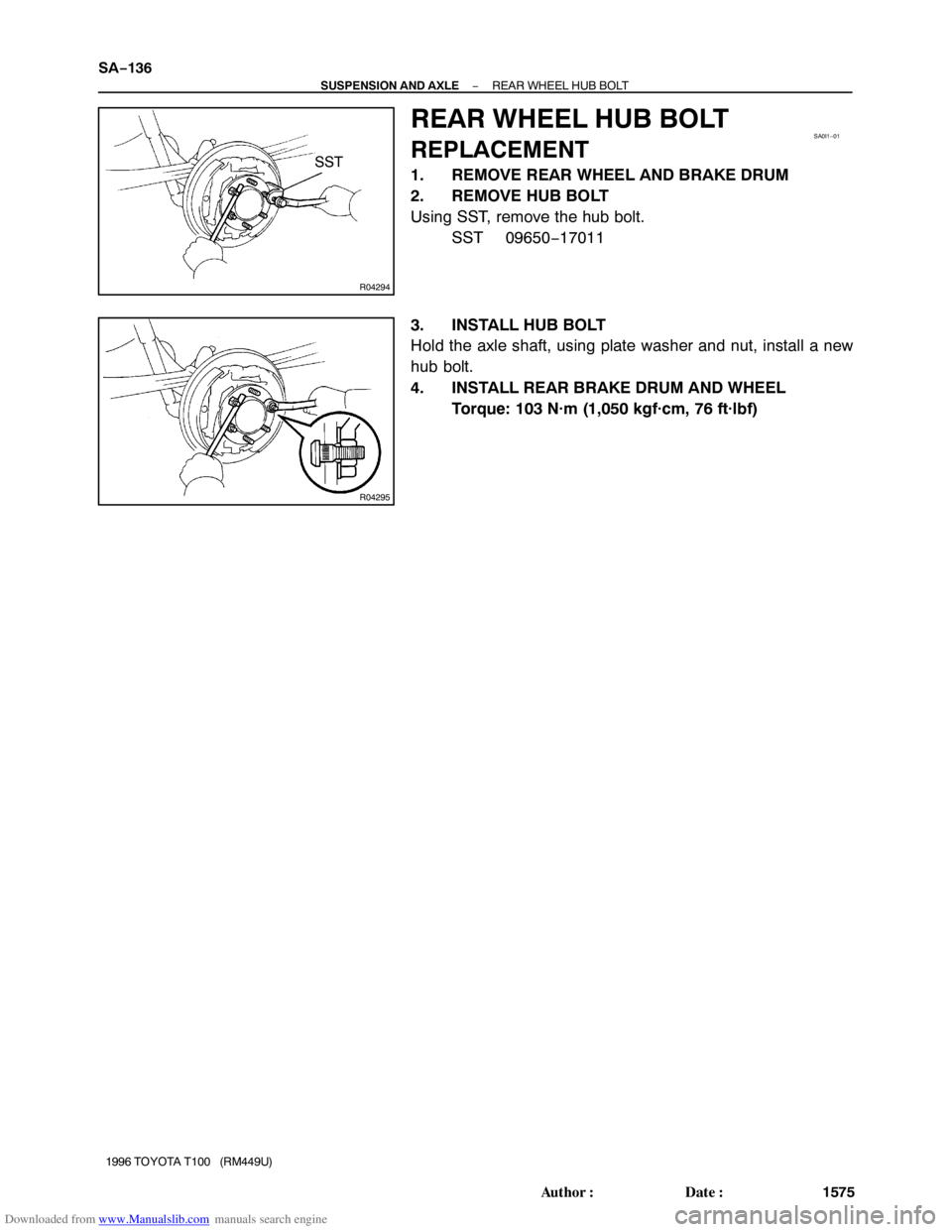
REAR WHEEL HUB BOLT
REPLACEMENT
1. REMOVE REAR WHEEL AND BRAKE DRUM
2. REMOVE HUB BOLT
Using SST, remove the hub bolt.
SST 09650−17011
3. INSTALL HUB BOLT
Hold the axle shaft, using plate washer and nut, install a new
hub bolt.
4. INSTALL REAR BRAKE DRUM AND WHEEL
Torque: 103 N·m (1,050 kgf·cm, 76 ft·lbf)
Page 1609 of 2062
Downloaded from www.Manualslib.com manuals search engine R04163
Matchmarks
SA0I3−01
R08285
− SUSPENSION AND AXLEREAR DIFFERENTIAL CARRIER
SA−139
1996 TOYOTA T100 (RM449U)
REMOVAL
1. DRAIN HYPOID GEAR OIL
2. REMOVE REAR AXLE SHAFTS (See page SA−131)
3. REMOVE PROPELLER SHAFT
(2WD: See page PR−3)
(4WD: See page PR−11)
4. REMOVE DIFFERENTIAL CARRIER ASSEMBLY
(a) Remove the 10 nuts, washers and differential carrier as-
sembly.
Torque: 73 N·m (740 kgf·cm, 54 ft·lbf)
NOTICE:
Be careful not to damage the installation surface.
(b) Remove the gasket.
Page 1616 of 2062

Downloaded from www.Manualslib.com manuals search engine R04333
SST
SST
SA1143
Boiling Water
R04332
Matchmarks
R04334
R04335
SST SA−146
− SUSPENSION AND AXLEREAR DIFFERENTIAL CARRIER
1996 TOYOTA T100 (RM449U)
2. INSTALL SIDE BEARINGS
Using SST and a press, install the 2 side bearings into the differ-
ential case.
SST 09506−35010, 09950−60010 (09951−00480),
09950−70010 (09951−07150)
3. INSTALL RING GEAR ON DIFFERENTIAL CASE
(a) Clean the contact surfaces of the differential case and
ring gear.
(b) Heat the ring gear to about 100°C (212°F) in boiling wa-
ter.
(c) Carefully take the ring gear out of the boiling water.
(d) After the moisture on the ring gear has completely evapo-
rated, quickly install the ring gear to the differential case.
(e) Align the matchmarks on the ring gear and differential
case.
(f) After the ring gear cools down enough, torque the set
bolts to which thread lock has been applied.
Thread lock:
Part No. 08833−00100, THREE BOND 1360K or equiv-
alent.
Torque: 125 N·m (1,270 kgf·cm, 92 ft·lbf)
4. INSPECT RING GEAR RUNOUT
(a) Install the differential case into the carrier and install the
plate washers to make sure the play in the bearing (See
page SA−57).
(b) Install bearing cap (See page SA−57).
(c) Using a dial indicator, measure the runout of ring gear.
Maximum runout: 0.05 mm (0.0020 in.)
5. INSTALL DRIVE PINION BEARING OUTER RACES
AND ADJUSTING WASHER
(a) Using SST, install a new front bearing outer race to the
carrier.
SST 09950−60020 (09951−00710),
09950−70010 (09951−07150)
(b) Using SST, install a new adjusting washer and install a
new rear bearing outer race to the carrier.
SST 09950−60020 (09951−00910),
09950−70010 (09951−07150)
Page 1617 of 2062

HINT:
First fit a")
Downloaded from www.Manualslib.com manuals search engine R00055
SST
R11163SST
SA2351
SST
SA2446
− SUSPENSION AND AXLEREAR DIFFERENTIAL CARRIER
SA−147
1996 TOYOTA T100 (RM449U)
HINT:
First fit a washer with the same thickness as the washer which
was removed, then after checking the tooth contact pattern, re-
place the washer with one of a different thickness if necessary.
6. INSTALL DRIVE PINION REAR BEARING
Using SST and a press, install the rear bearing onto the drive
pinion.
SST 09506−35010
7. TEMPORARILY ADJUST DRIVE PINION PRELOAD
(a) Install the drive pinion and front bearing.
HINT:
Assemble the spacer, washers and oil seal after adjusting the
gear contact pattern.
(b) Using SST, install the companion flange.
SST 09950−30010
(c) Coat the threads of the nut with hypoid gear oil.
(d) Adjust the drive pinion preload by tightening the compan-
ion flange nut.
Using SST to hold the flange, torque the nut.
SST 09330−00021
NOTICE:
As there is no spacer, tighten the nut a little at a time, being
careful not to overtighten it.
(e) Using a torque wrench, measure the preload.
Preload (at starting):
New bearing:
1.0 − 1.6 N·m (10 − 16 kgf·cm, 8.7 − 13.9 in.·lbf)
Reused bearing:
0.5 − 0.8 N·m (5 − 8 kgf·cm, 4.3 − 6.9 in.·lbf)

1996 TOYOTA T100 (RM449U)
REMOVAL
1. REMOVE FRONT WHEEL
T")

SA−127
1996 TOYOTA T100 (RM449U)
REMOVAL
REMOVE STABILIZER BAR
(")

REMOVAL
1. DRAIN HYPO")