Page 1513 of 2062

Downloaded from www.Manualslib.com manuals search engine SA0G3−02
Z00638
SST
B4056 B4057
R11389
SST
SA0505
SST
SA0507
SST
Z03906
SST
1.5 mm (0.059 in.)
Drive in Depth
− SUSPENSION AND AXLEFRONT DIFFERENTIAL REAR OIL SEAL (4WD)
SA−43
1996 TOYOTA T100 (RM449U)
REPLACEMENT
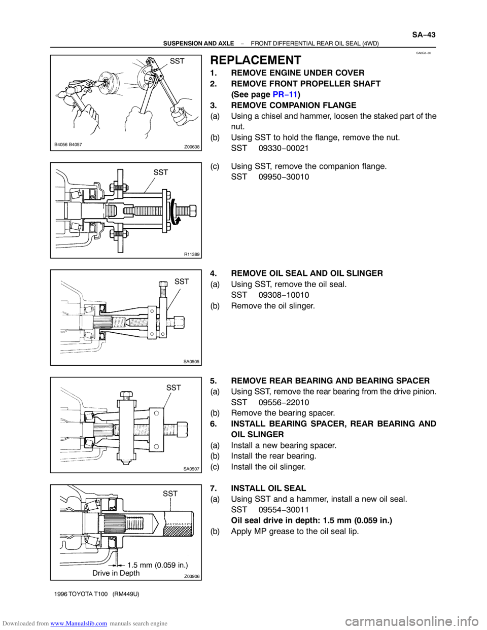
1. REMOVE ENGINE UNDER COVER
2. REMOVE FRONT PROPELLER SHAFT
(See page PR−11)
3. REMOVE COMPANION FLANGE
(a) Using a chisel and hammer, loosen the staked part of the
nut.
(b) Using SST to hold the flange, remove the nut.
SST 09330−00021
(c) Using SST, remove the companion flange.
SST 09950−30010
4. REMOVE OIL SEAL AND OIL SLINGER
(a) Using SST, remove the oil seal.
SST 09308−10010
(b) Remove the oil slinger.
5. REMOVE REAR BEARING AND BEARING SPACER
(a) Using SST, remove the rear bearing from the drive pinion.
SST 09556−22010
(b) Remove the bearing spacer.
6. INSTALL BEARING SPACER, REAR BEARING AND
OIL SLINGER
(a) Install a new bearing spacer.
(b) Install the rear bearing.
(c) Install the oil slinger.
7. INSTALL OIL SEAL
(a) Using SST and a hammer, install a new oil seal.
SST 09554−30011
Oil seal drive in depth: 1.5 mm (0.059 in.)
(b) Apply MP grease to the oil seal lip.
Page 1514 of 2062
Downloaded from www.Manualslib.com manuals search engine R12169
SST
FA1083
SST
R04344
Less than 5 mm (0.20 in.) SA−44
− SUSPENSION AND AXLEFRONT DIFFERENTIAL REAR OIL SEAL (4WD)
1996 TOYOTA T100 (RM449U)
8. INSTALL COMPANION FLANGE
(a) Using SST, install the companion flange on the drive pin-
ion.
SST 09950−30010
(b) Apply light coat of hypoid gear oil on threads of a new
companion flange nut.
(c) Using SST to hold the flange, torque the nut.
SST 09330−00021
Torque: 108 N·m (1,100 kgf·cm, 80 ft·lbf)
9. ADJUST DRIVE PINION PRELOAD
(See page SA−57)
10. STAKE DRIVE PINION NUT
11. INSTALL FRONT PROPELLER SHAFT
(See page PR−16)
12. FILL DIFFERENTIAL WITH HYPOID GEAR OIL
Torque:
Drain plug: 49 N·m (500 kgf·cm, 36 ft·lbf)
Filler plug: 39 N·m (400 kgf·cm, 29 ft·lbf)
Oil type: Hypoid gear oil API GL−5
Recommended oil viscosity: SAE 75W−90
Capacity: 1.86 liters (1.97 US qts, 1.64 lmp. qts)
13. INSTALL ENGINE UNDER COVER
Page 1515 of 2062
Downloaded from www.Manualslib.com manuals search engine SA0G4−03
− SUSPENSION AND AXLEFRONT DIFFERENTIAL CARRIER (4WD)
SA−45
1484 Author�: Date�:
1996 TOYOTA T100 (RM449U)
FRONT DIFFERENTIAL CARRIER (4WD)
COMPONENTS
Page 1516 of 2062
Downloaded from www.Manualslib.com manuals search engine SA−46
− SUSPENSION AND AXLEFRONT DIFFERENTIAL CARRIER (4WD)
1485 Author�: Date�:
1996 TOYOTA T100 (RM449U)
Page 1517 of 2062

Downloaded from www.Manualslib.com manuals search engine SA0G5−01
R04298
Matchmarks
R04533
FA0858
− SUSPENSION AND AXLEFRONT DIFFERENTIAL CARRIER (4WD)
SA−47
1996 TOYOTA T100 (RM449U)
REMOVAL
1. REMOVE ENGINE UNDER COVER AND DRAIN HYPO-
ID GEAR OIL
2. REMOVE FRONT PROPELLER SHAFT
(See page PR−11)
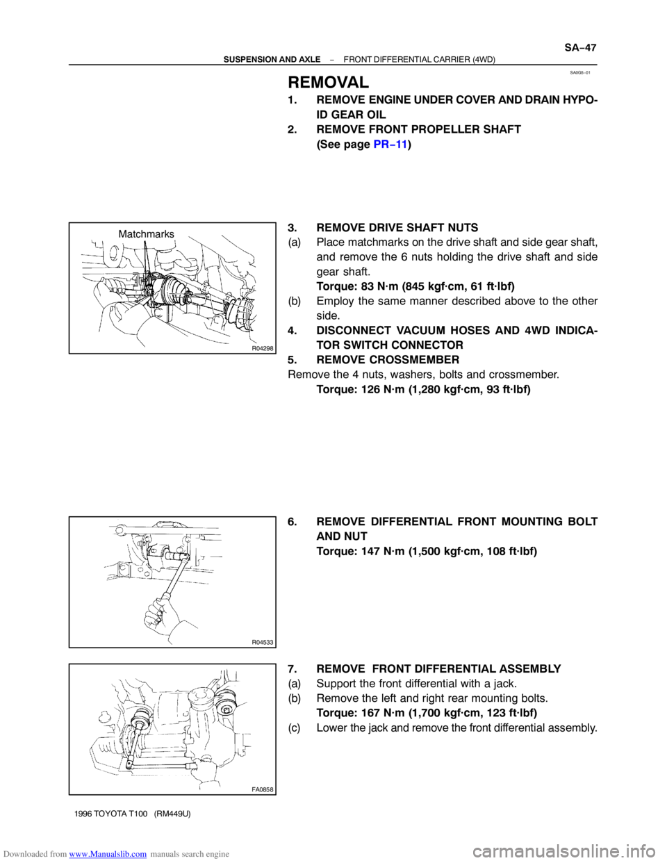
3. REMOVE DRIVE SHAFT NUTS
(a) Place matchmarks on the drive shaft and side gear shaft,
and remove the 6 nuts holding the drive shaft and side
gear shaft.
Torque: 83 N·m (845 kgf·cm, 61 ft·lbf)
(b) Employ the same manner described above to the other
side.
4. DISCONNECT VACUUM HOSES AND 4WD INDICA-
TOR SWITCH CONNECTOR
5. REMOVE CROSSMEMBER
Remove the 4 nuts, washers, bolts and crossmember.
Torque: 126 N·m (1,280 kgf·cm, 93 ft·lbf)
6. REMOVE DIFFERENTIAL FRONT MOUNTING BOLT
AND NUT
Torque: 147 N·m (1,500 kgf·cm, 108 ft·lbf)
7. REMOVE FRONT DIFFERENTIAL ASSEMBLY
(a) Support the front differential with a jack.
(b) Remove the left and right rear mounting bolts.
Torque: 167 N·m (1,700 kgf·cm, 123 ft·lbf)
(c) Lower the jack and remove the front differential assembly.
Page 1518 of 2062

Downloaded from www.Manualslib.com manuals search engine W00493
30 mm
(1.18 in.)
SA258−01
SA2352
W00400
SA0344
SA−48
− SUSPENSION AND AXLEFRONT DIFFERENTIAL CARRIER (4WD)
1996 TOYOTA T100 (RM449U)
DISASSEMBLY
1. CHECK RUNOUT OF COMPANION FLANGE
Using a dial indicator, measure the runout of the companion
flange vertical and lateral.
Maximum
Vertical runout: 0.10 mm (0.0039 in.)
Lateral runout: 0.10 mm (0.0039 in.)
2. MEASURE DRIVE PINION PRELOAD
Using a torque wrench, measure the drive pinion preload using
the backlash of the drive pinion and ring gear.
Preload (at starting):
0.6 − 1.0 N·m (6 − 10 kgf·cm, 5.2 − 8.7 in.·lbf)
If the runout is greater than the maximum, replace the compan-
ion flange.
3. CHECK TOTAL PRELOAD
Using a torque wrench, measure the total preload.
Total preload (at starting):
Drive pinion preload plus
0.4 − 0.6 N·m (4 − 6 kgf·cm, 3.5 − 5.2 in.·lbf)
If necessary, disassemble and inspect the differential.
4. REMOVE A.D.D. ACTUATOR
(a) Remove the 4 bolts.
(b) Using a hammer handle, remove the actuator.
5. REMOVE DIFFERENTIAL CARRIER COVER
Remove the 8 bolts and tap out the cover with a plastic hammer.
6. CHECK SIDE GEAR BACKLASH
Using a dial indicator, measure the side gear backlash with
holding one pinion gear toward the differential case.
Backlash: 0.05 − 0.20 mm (0.0020 − 0.0079 in.)
If the backlash is out of specification, install the correct thrust
washers (See page SA−57).
Page 1519 of 2062
Downloaded from www.Manualslib.com manuals search engine SA0346
SA0349
SA0337
SST
SA0352
SST
R11390
SST
SST
− SUSPENSION AND AXLEFRONT DIFFERENTIAL CARRIER (4WD)
SA−49
1996 TOYOTA T100 (RM449U)
7. REMOVE LH SIDE GEAR SHAFT WITH TUBE
(a) Using a torx socket (E14), remove the 4 torx bolts.
(b) Using a plastic hammer, tap on the tube to remove it.
(c) Remove the sleeve.
(d) Remove the O−ring from the tube.
8. REMOVE CLUTCH CASE
(a) Using a torx socket (E14), remove the 2 torx bolts.
(b) Using a plastic hammer, tap on the clutch case to remove
it.
9. REMOVE RH SIDE GEAR SHAFT
Using SST, remove the side gear shaft.
SST 09910−00015 (09911−00011, 09912−00010,
09914−00011)
10. REMOVE RH SIDE GEAR SHAFT OIL SEAL
Using SST, remove the right side gear shaft oil seal.
SST 09308−00010
11. REMOVE INTERMEDIATE SHAFT
Using SST, remove the intermediate shaft.
SST 09350−20015 (09369−20040), 09950−40010
Page 1520 of 2062

Downloaded from www.Manualslib.com manuals search engine Z03854
Z03853
Z03852
SA2349
SST
R11391SST SA−50
− SUSPENSION AND AXLEFRONT DIFFERENTIAL CARRIER (4WD)
1996 TOYOTA T100 (RM449U)
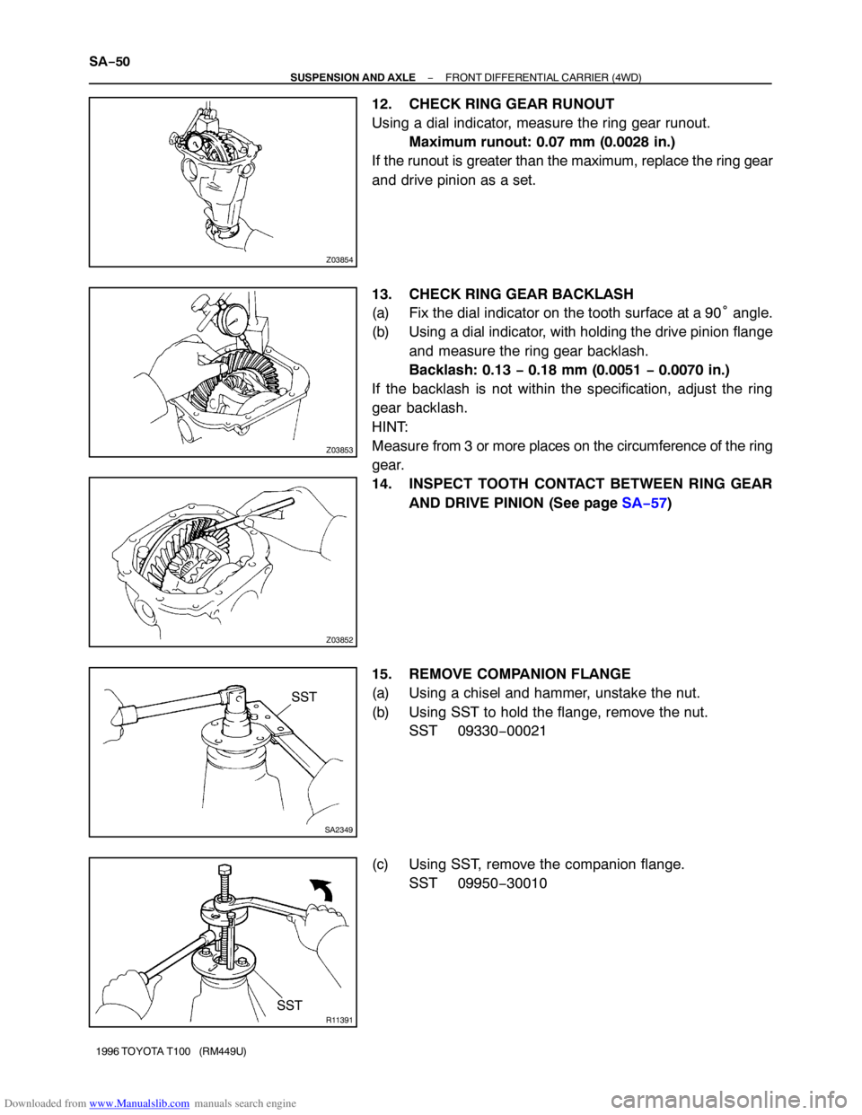
12. CHECK RING GEAR RUNOUT
Using a dial indicator, measure the ring gear runout.
Maximum runout: 0.07 mm (0.0028 in.)
If the runout is greater than the maximum, replace the ring gear
and drive pinion as a set.
13. CHECK RING GEAR BACKLASH
(a) Fix the dial indicator on the tooth surface at a 90° angle.
(b) Using a dial indicator, with holding the drive pinion flange
and measure the ring gear backlash.
Backlash: 0.13 − 0.18 mm (0.0051 − 0.0070 in.)
If the backlash is not within the specification, adjust the ring
gear backlash.
HINT:
Measure from 3 or more places on the circumference of the ring
gear.
14. INSPECT TOOTH CONTACT BETWEEN RING GEAR
AND DRIVE PINION (See page SA−57)
15. REMOVE COMPANION FLANGE
(a) Using a chisel and hammer, unstake the nut.
(b) Using SST to hold the flange, remove the nut.
SST 09330−00021
(c) Using SST, remove the companion flange.
SST 09950−30010