Page 1497 of 2062
Downloaded from www.Manualslib.com manuals search engine SA0FQ−01
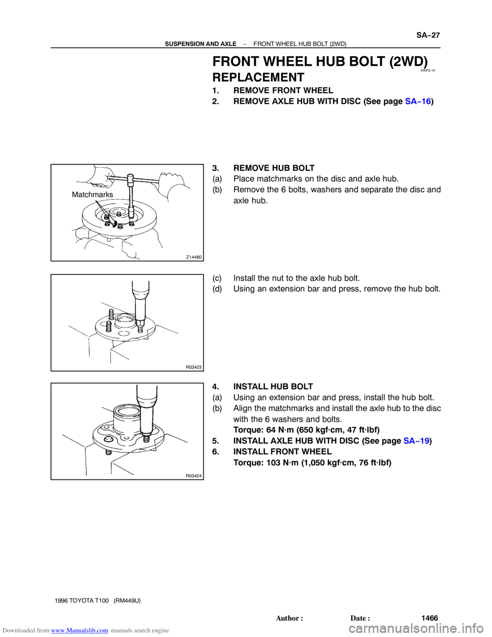
Z14480
Matchmarks
R03423
R03424
− SUSPENSION AND AXLEFRONT WHEEL HUB BOLT (2WD)
SA−27
1466 Author�: Date�:
1996 TOYOTA T100 (RM449U)
FRONT WHEEL HUB BOLT (2WD)
REPLACEMENT
1. REMOVE FRONT WHEEL
2. REMOVE AXLE HUB WITH DISC (See page SA−16)
3. REMOVE HUB BOLT
(a) Place matchmarks on the disc and axle hub.
(b) Remove the 6 bolts, washers and separate the disc and
axle hub.
(c) Install the nut to the axle hub bolt.
(d) Using an extension bar and press, remove the hub bolt.
4. INSTALL HUB BOLT
(a) Using an extension bar and press, install the hub bolt.
(b) Align the matchmarks and install the axle hub to the disc
with the 6 washers and bolts.
Torque: 64 N·m (650 kgf·cm, 47 ft·lbf)
5. INSTALL AXLE HUB WITH DISC (See page SA−19)
6. INSTALL FRONT WHEEL
Torque: 103 N·m (1,050 kgf·cm, 76 ft·lbf)
Page 1498 of 2062
Downloaded from www.Manualslib.com manuals search engine SA0FR−02
SA−28
− SUSPENSION AND AXLESTEERING KNUCKLE (4WD)
1467 Author�: Date�:
1996 TOYOTA T100 (RM449U)
STEERING KNUCKLE (4WD)
COMPONENTS
Page 1499 of 2062

SA−29
1996 TOYOTA T100 (RM449U)
REMOVAL
1. REMOVE BRAK")
Downloaded from www.Manualslib.com manuals search engine SA0FS−01
R04382
FA0781
R04383
R04384
− SUSPENSION AND AXLESTEERING KNUCKLE (4WD)
SA−29
1996 TOYOTA T100 (RM449U)
REMOVAL
1. REMOVE BRAKE CALIPER AND FRONT AXLE HUB
(See page SA−23)
2. REMOVE DUST COVER AND OIL SEAL
3. MEASURE STEERING KNUCKLE BUSHING THRUST
CLEARANCE
(a) Install a bolt in the drive shaft.
(b) Using a feeler gauge, measure the drive shaft thrust
clearance between the steering knuckle outside bushing
and spacer, by pulling the bolt and applying a load of 98
N (10 kgf, 22.0 lbf).
Front drive shaft thrust clearance:
Standard: 0.10 − 0.50 mm (0.0039 − 0.0197 in.)
Maximum: 1.0 mm (0.039 in.)
If the thrust clearance than the maximum, replace the steering
knuckle outside and inside bushings.
4. DISCONNECT FRONT SHOCK ABSORBER FROM
LOWER SUSPENSION ARM
Remove the nut, washer, bolt and shock absorber from the low-
er suspension arm.
5. DISCONNECT STABILIZER BAR FROM LOWER
SUSPENSION ARM
(a) Remove the nut, bolt, 5 retainers, 4 cushions and collar.
(b) Disconnect the stabilizer bar from the lower suspension
arm.
Page 1500 of 2062
Downloaded from www.Manualslib.com manuals search engine R12263
SST
FA0873
SA−30
− SUSPENSION AND AXLESTEERING KNUCKLE (4WD)
1996 TOYOTA T100 (RM449U)
6. REMOVE STEERING KNUCKLE
(a) Using snap ring pliers, remove the snap ring and spacer.
(b) Support the lower suspension arm with a jack.
(c) Remove the cotter pin and nut from the upper ball joint.
(d) Using SST, disconnect the steering knuckle from the up-
per ball joint.
SST 09628−62011
(e) Remove the 4 bolts from the lower ball joint and discon-
nect the steering knuckle from the lower ball joint.
(f) Push down the lower suspension arm and remove the
steering knuckle.
NOTICE:
Be careful not to damage the oil seal and boot.
Page 1501 of 2062
Downloaded from www.Manualslib.com manuals search engine SA0FT−01
FA0786
SST
− SUSPENSION AND AXLESTEERING KNUCKLE (4WD)
SA−31
1996 TOYOTA T100 (RM449U)
DISASSEMBLY
1. REMOVE DUST COVER
Using a screwdriver and hammer, remove the dust cover from
the steering knuckle.
2. REMOVE STEERING KNUCKLE BUSHING
(a) Using SST, remove the steering knuckle outside bushing.
SST 09308−00010
(b) Using a brass bar and hammer, remove the steering
knuckle needle roller bearing and inside bushing.
Page 1502 of 2062
Downloaded from www.Manualslib.com manuals search engine SA0FU−01
FA0735
SA−32
− SUSPENSION AND AXLESTEERING KNUCKLE (4WD)
1996 TOYOTA T100 (RM449U)
INSPECTION
INSPECT STEERING KNUCKLE
Using a dye penetrant, check the steering knuckle for cracks.
Page 1503 of 2062

SA−")
Downloaded from www.Manualslib.com manuals search engine SA0FV−02
W00456
SST
W00458
SST
Knuckle
Needle
Roller Bearing SSTThrust
Bushing
R04291
SST
− SUSPENSION AND AXLESTEERING KNUCKLE (4WD)
SA−33
1996 TOYOTA T100 (RM449U)
REASSEMBLY
1. INSTALL STEERING KNUCKLE BUSHING
(a) Using SST and a press, install a new steering knuckle out-
side bushing.
SST 09950−60010 (09951−00360),
09950−70010 (09951−07150)
HINT:
When installing the bushing to the spindle, make sure the flat
portion of the bushing is aligned with the spindle groove, as
shown in the illustration.
(b) Using SST and a press, install a new needle roller bear-
ing, as shown in the illustration.
SST 09950−60010 (09951−00360),
09950−70010 (09951−07150)
HINT:
�Bearing must be installed with flat side which has I.D. and
part number facing outward.
�Press the bearing in until the top surface of the bearing is
in approx. 2 − 3 mm (0.08 − 0.12 in.) inside the knuckle
surface.
(c) Using SST and a press, install a new thrust bushing.
SST 09950−60010 (09951−00500),
09950−70010 (09951−07150)
(d) Apply synthetic oil and lithium soap base chassis grease,
NLGI No.1 to the steering knuckle inner side of thrust
bushing.
2. INSTALL DUST DEFLECTOR TO STEERING
KNUCKLE
Using SST and a hammer, install a new dust deflector.
SST 09950−60020 (09951−00910),
09950−70010 (09951−07150)
Page 1504 of 2062

1996 TOYOTA T100 (RM449U)
INSTALLATION
1. INSTALL STEER")
Downloaded from www.Manualslib.com manuals search engine SA0FW−02
R04389
FA0781
Z03703
SA−34
− SUSPENSION AND AXLESTEERING KNUCKLE (4WD)
1996 TOYOTA T100 (RM449U)
INSTALLATION
1. INSTALL STEERING KNUCKLE
(a) Apply synthetic oil and lithium soap base chassis grease,
NLGI No.1 to the drive shaft.
(b) Push down the lower suspension arm and install the
steering knuckle.
NOTICE:
Be careful not to damage the oil seal and boot.
(c) Connect the lower ball joint to the steering knuckle, install
and torque the nut.
Torque: 142 N·m (1,450 kgf·cm, 105 ft·lbf)
(d) Install a new cotter pin.
(e) Connect the upper ball joint to the steering knuckle, install
and torque the 4 nuts.
Torque: 142 N·m (1,450 kgf·cm, 105 ft·lbf)
(f) Install a new cotter pin.
(g) Install the spacer to the drive shaft.
(h) Using snap ring pliers, install the snap ring.
NOTICE:
If you replace the steering knuckle bushing, recheck the
drive shaft thrust clearance.
(i) Install the bolt in the drive shaft.
(j) Using a feeler gauge, measure the drive shaft thrust
clearance between the steering knuckle outside bushing
and spacer, by pulling the bolt and applying a load of 98
N (10 kgf, 22.0 lbf).
Front drive shaft thrust clearance:
Standard: 0.10 − 0.50 mm (0.0039 − 0.0197 in.)
If the clearance is not within specification, replace the spacer.
Spacer thickness
1.80 mm (0.0709 in.)2.25 mm (0.0886 in.)
2. CONNECT STABILIZER BAR TO LOWER
SUSPENSION ARM
(a) Connect the stabilizer bar to the lower suspension arm
with the bolt, 5 retainers, 4 cushions, collar and a new nut,
as shown in the illustration.
(b) Torque the nut.
Torque: 25 N·m (260 kgf·cm, 19 ft·lbf)


1996 TOYOTA T100 (RM449U)
6. REMOVE STEERING KNUCKLE
(a) Using snap r")

SA−31
1996 TOYOTA T100 (RM449U)
DISASSEMBLY
1. REMOVE DUST COVER
Using")

1996 TOYOTA T100 (RM449U)
INSPECTION
INSPECT STEERING KNUCKLE
Using a")