Page 24 of 2062

Downloaded from www.Manualslib.com manuals search engine V07469
HEAT METHOD: When the problem seems to occur when the suspect area is heated. 2
NOTICE:
(1) Do not heat to more than 60 °C (140 °F). (Temperature
is limited not to damage the components.)
(2) Do not apply heat directly to parts in the ECU.
3 WATER SPRINKLING METHOD:
NOTICE:
(1) Never sprinkle water directly into the engine
compartment, but indirectly change the temperature and
humidity by applying water spray onto the radiator front
surface.
(2) Never apply water directly onto the electronic
components.
4 OTHER: When a malfunction seems to occur when electrical load is excessive.When the malfunction seems to occur on a rainy day or in a
high−humidity condition. Heat the component that is the likely cause of the malfunction
with a hair dryer or similar object. Check to see if the malfunction
occurs.
Sprinkle water onto the vehicle and check to see if the malfunc-
tion occurs.
Turn on all electrical loads including the heater blower, head
lights, rear window defogger, etc. and check to see if the mal-
function occurs.ON (Service hint)
If a vehicle is subject to water leakage, the leaked water may
contaminate the ECU. When testing a vehicle with a water leak-
age problem, special caution must be taken.
Malfunc-
tion
− INTRODUCTIONHOW TO TROUBLESHOOT ECU CONTROLLED
SYSTEMSIN−21
1996 TOYOTA T100 (RM449U)
Page 175 of 2062
Downloaded from www.Manualslib.com manuals search engine PP33S−02
− PREPARATIONBODY
PP−121
1996 TOYOTA T100 (RM449U)
SSM (Special Service Materials)
08833−00030Three cement black or equivalentWindshield Moulding
Windshield
Back Window Glass
08833−00070Adhesive 1324,
THREE BOND 1324 or equivalentFront Door
08850−00070Windshield glass adhesive set
No.15 or equivalentWindshield
Back WindowGlass
(0−15 °C or 32 − 59 °F)
08850−00080Windshield glass adhesive set
No.35 or equivalentWindshield
Back WindowGlass
(35 − 45 °C or 59 − 95 °F)
08850−00090Windshield glass adhesive set
No.45 or equivalentWindshield
Back WindowGlass
(35−45 °C or 95 − 95 °F)
08850−00801Windshield Glass Adhesive Set
or equivalentWindshield
Page 260 of 2062

Downloaded from www.Manualslib.com manuals search engine SS08Y−02
SS−80
− SERVICE SPECIFICATIONSBODY
254 Author�: Date�:
1996 TOYOTA T100 (RM449U)
BODY
TORQUE SPECIFICATION
Part tightenedN·mkgf·cmft·lbf
FRONT BUMPER−−−
Front bumper arm x Body6162045
Bumper side support x Bumper arm131309
HOOD−−−
Hood hinge x Hood1414510
Hood lock x Body1919514
FRONT DOOR−−−
Door hinge x Body2526019
Door hinge x Door panel2526019
Door lock x Door panel5.96052 in.·lbf
Window regulator x Door panel5.45548 in.·lbf
FRONT WIPER AND WASHER−−−
Wiper arm x Wiper link2020415
TAIL GATE−−−
Tail gate lock striker x Body121209
Tail gate lock x Tail gate121209
Tail gate hinge x Tail gate1818513
FRONT SEAT (Bench Type)−−−
Seat track x Body3737527
Seat track x Seatback1818513
Outer track x Seat cushion frame1818513
Inner track x Seat cushion frame1818513
FRONT SEAT (Split Bench Type)−−−
Seat track x Body3737527
Seat adjuster x Seatback1818513
Outer track x Seat cushion frame1818513
Inner track x Seat cushion frame1818513
Seat adjuster x Seat cushion frame1818513
Inner track x Seat back frame12.51309.5
REAR SEAT−−−
Back panel trim x Body9.81007
Seat cushion x Body9.81007
SEAT BELT−−−
Front Seat Belt−−−
Adjustable anchor x Body4344032
Shoulder anchor x Adjustable anchor4344032
ELR x Body4344032
Lap outer anchor x Body4344032
Inner belt x Body4344032
Rear Seat Belt−−−
Shoulder anchor x Body4344032
ELR x Body4344032
Page 1814 of 2062
Downloaded from www.Manualslib.com manuals search engine SST
R13455
SSTBattery
− SUPPLEMENTAL RESTRAINT SYSTEMSTEERING WHEEL PAD AND SPIRAL CABLE
RS−13
1996 TOYOTA T100 (RM449U)
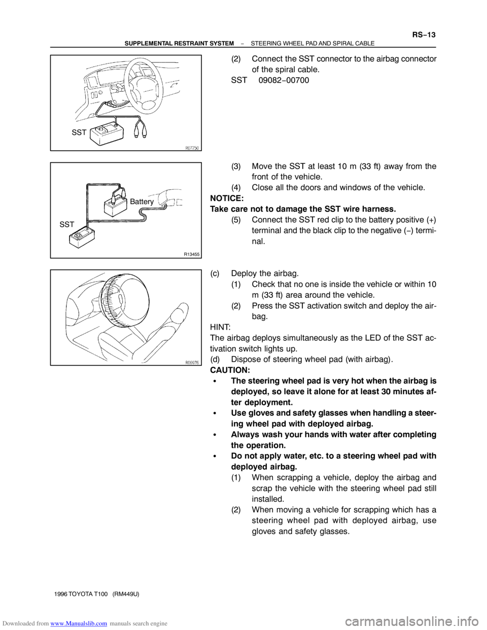
(2) Connect the SST connector to the airbag connector
of the spiral cable.
SST 09082−00700
(3) Move the SST at least 10 m (33 ft) away from the
front of the vehicle.
(4) Close all the doors and windows of the vehicle.
NOTICE:
Take care not to damage the SST wire harness.
(5) Connect the SST red clip to the battery positive (+)
terminal and the black clip to the negative (−) termi-
nal.
(c) Deploy the airbag.
(1) Check that no one is inside the vehicle or within 10
m (33 ft) area around the vehicle.
(2) Press the SST activation switch and deploy the air-
bag.
HINT:
The airbag deploys simultaneously as the LED of the SST ac-
tivation switch lights up.
(d) Dispose of steering wheel pad (with airbag).
CAUTION:
�The steering wheel pad is very hot when the airbag is
deployed, so leave it alone for at least 30 minutes af-
ter deployment.
�Use gloves and safety glasses when handling a steer-
ing wheel pad with deployed airbag.
�Always wash your hands with water after completing
the operation.
�Do not apply water, etc. to a steering wheel pad with
deployed airbag.
(1) When scrapping a vehicle, deploy the airbag and
scrap the vehicle with the steering wheel pad still
installed.
(2) When moving a vehicle for scrapping which has a
steering wheel pad with deployed airbag, use
gloves and safety glasses.
Page 1835 of 2062
Downloaded from www.Manualslib.com manuals search engine BE – BODY ELECTRICAL
BODY ELECTRICAL SYSTEM BE-1
POWER SOURCE BE-10
IGNITION SWITCH AND KEY UNLOCK
WARNING SWITCH BE-11
HEADLIGHT AND TAILLIGHT SYSTEM BE-14
TURN SIGNAL AND HAZARD
WARNING SYSTEM BE-22
INTERIOR LIGHT SYSTEM BE-24
BACK-UP LIGHT SYSTEM BE-26
STOP LIGHT SYSTEM BE-29
WIPER AND WASHER SYSTEM BE-31
COMBINATION METER BE-35
POWER WINDOW CONTROL SYSTEM BE-46
POWER DOOR LOCK CONTROL
SYSTEM BE-50
POWER MIRROR CONTROL SYSTEM BE-56
AUDIO SYSTEM BE-59
ANTENNA BE-81
CLOCK BE-83
Page 1843 of 2062
Downloaded from www.Manualslib.com manuals search engine BE−8
− BODY ELECTRICALBODY ELECTRICAL SYSTEM
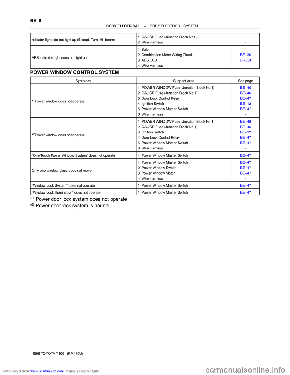
1996 TOYOTA T100 (RM449U) ndicator lights do not light up (Except. Turn, Hi−beam)
1. GAUGE Fuse (Junction Block No1.)
2. Wire Harness−
−
ABS indicator light does not light up
1. Bulb
2. Combination Meter Wiring Circuit
3. ABS ECU
4. Wire Harness−
BE−36
DI−331
−
POWER WINDOW CONTROL SYSTEM
SymptomSuspect AreaSee page
*1Power window does not operate
1. POWER WINDOW Fuse (Junction Block No.1)
2. GAUGE Fuse (Junction Block No.1)
3. Door Lock Control Relay
4. Ignition Switch
5. Power Window Master Switch
6. Wire HarnessBE−46
BE−46
BE−47
BE−12
BE−47
−
*2Power window does not operate
1. POWER WINDOW Fuse (Junction Block No.1)
2. GAUGE Fuse (Junction Block No.1)
3. Ignition Switch
4. Door Lock Control Relay
5. Power Window Master Switch
6. Wire HarnessBE−46
BE−46
BE−12
BE−47
BE−47
−
”One Touch Power Window System” does not operate1. Power Window Master SwitchBE−47
Only one window glass does not move
1. Power Window Master Switch
2. Power Window Switch
3. Power Window Motor
4. Wire HarnessBE−47
BE−47
BE−47
−
”Window Lock System” does not operate1. Power Window Master SwitchBE−47
”Window Lock Illumination” does not operate1. Power Window Master SwitchBE−47
*1 Power door lock system does not operate
*
2 Power door lock system is normal
Page 1844 of 2062
Downloaded from www.Manualslib.com manuals search engine − BODY ELECTRICALBODY ELECTRICAL SYSTEM
BE−9
1996 TOYOTA T100 (RM449U)
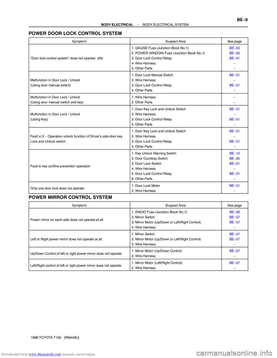
POWER DOOR LOCK CONTROL SYSTEM
SymptomSuspect AreaSee page
”Door lock control system” does not operate (All)
1. GAUGE Fuse (Junction Block No.1)
2. POWER WINDOW Fuse (Junction Block No.1)
3. Door Lock Control Relay
4. Wire Harness
5. Other PartsBE−50
BE−50
BE−51
−
−
Malfunction in Door Lock / Unlock
(Using door manual switch)
1. Door Lock Manual Switch
2. Wire Harness
3. Door Lock Control Relay
4. Other PartsBE−51
−
BE−51
−
Mulfunction in Door Lock / Unlock
(Using door manual switch and key)1. Wire Harness
2. Other Parts−
−
Mulfunction in Door Lock / Unlock
(Using Key)
1. Door Key Lock and Unlock Switch
2. Wire Harness
3. Door Lock Control Relay
4. Other PartsBE−51
−
BE−51
−
Fault in 2 − Operation unlock function of Driver’s side door key
Lock and Unlock switch
1. Door Key Lock and Unlock Switch
2. Wire Harness
3. Door Lock Control Relay
4. Other PartsBE−51
−
BE−51
−
Fault in key confine prevention operation
1. Key Unlock Warning Switch
2. Door Courtesy Switch
3. Door Lock Switch
4. Wire Harness
5. Door Lock Control Relay
6. Other PartsBE−12
BE−25
BE−51
−
BE−51
−
Only one door lock does not operate1. Door Lock Motor
2. Wire HarnessBE−51
−
POWER MIRROR CONTROL SYSTEM
SymptomSuspect AreaSee page
Power mirror on each side does not operate at all
1. RADIO Fuse (Junction Block No.1)
2. Mirror Switch
3. Mirror Motor (Up/Down or Left/Right Control)
4. Wire HarnessBE−56
BE−57
BE−57
−
Left or Right power mirror does not operate at all
1. Mirror Switch
2. Mirror Motor (Up/Down or Left/Right Control)
3. Wire HarnessBE−57
BE−57
−
Up/Down Control of left or right power mirror does not operate1. Mirror Motor (Up/Down Control)
2. Wire HarnessBE−57
−
Left/Right control of left or right power mirror does not operate1. Mirror Motor (Left/Right Control)
2. Wire HarnessBE−57
−
Page 1881 of 2062
Downloaded from www.Manualslib.com manuals search engine BE03O−04
N13075
Power Window Master Switch
Ignition Switch
Power Window Switch
Power Window Motor Door Lock Control RelayJunction Block No.1
� GAUGE Fuse
� POWER WINDOW Fuse BE−46
− BODY ELECTRICALPOWER WINDOW CONTROL SYSTEM
1846 Author�: Date�:
1996 TOYOTA T100 (RM449U)
POWER WINDOW CONTROL SYSTEM
LOCATION


