Page 1465 of 2062

Downloaded from www.Manualslib.com manuals search engine Z03925
Matchmarks
MatchmarksPR01S−01
Z16099
PR0019
SST
A
R04419
SST PR−18
− PROPELLER SHAFTSPIDER BEARING
1436 Author�: Date�:
1996 TOYOTA T100 (RM449U)
SPIDER BEARING
REPLACEMENT
1. PLACE MATCHMARKS ON SHAFT AND YOKE
2. REMOVE SNAP RING
(a) Using a brass bar and hammer, slightly tap in the bearing
outer race.
(b) 2WD (TMC−made) and 4WD:
Using 2 screwdrivers, remove the 4 snap rings from the
grooves.
(c) 2WD (DANA−made):
Using a long nosed plier, remove the 4 snap rings from the
grooves.
3. REMOVE SPIDER BEARING
(a) Using SST, push out the bearing from the flange.
SST 09332−25010
HINT:
Sufficiently raise the part indicated by ”A” so that it does not
come into contact with the bearing.
(b) Clamp the bearing outer race in a vise and tap off the
flange with a hammer.
HINT:
Remove the bearing on the opposite side in the same proce-
dure.
(c) Install the 2 removed bearing outer races to the spider.
(d) Using SST, push out the bearing from the yoke.
SST 09332−25010
(e) Clamp the outer bearing race in a vise and tap off the yoke
with a hammer.
HINT:
Remove the bearing on the opposite side in the same proce-
dure.
Page 1466 of 2062
Downloaded from www.Manualslib.com manuals search engine R04421
Color
Bearing
CapDrill Mark
Drill MarkYoke
Z00735
PR0027
SST
PR0028
R16052
− PROPELLER SHAFTSPIDER BEARING
PR−19
1437 Author�: Date�:
1996 TOYOTA T100 (RM449U)
4. SELECT SPIDER BEARING
Select the appropriate bearing according to the existence of
drill mark on the yoke.
YokeBearing
With drill markWith color mark (Red)
No drill markNo color mark
5. INSTALL SPIDER BEARING
(a) Apply MP grease to the spider and bearings.
HINT:
Be careful not to apply too much grease.
(b) Align the matchmarks on the yoke and shaft.
(c) Fit a new spider into the yoke.
(d) Using SST, install a new bearing on the spider.
SST 09332−25010
(e) Using SST, adjust both bearings so that the snap ring
grooves are at maximum and equal in width.
6. INSTALL SNAP RINGS
(a) Install 2 new snap rings of equal thickness which will allow
0 − 0.05 mm (0 − 0.0020 in.) axial play.
HINT:
Do not reuse the snap rings.
Page 1467 of 2062

Downloaded from www.Manualslib.com manuals search engine R16053
R04428
PR−20
− PROPELLER SHAFTSPIDER BEARING
1438 Author�: Date�:
1996 TOYOTA T100 (RM449U)
2WD (TMC−made) and 4WD:
ColorMarkThickness mm (in.)
−12.100 − 2.150
(0.0827 − 0.0846)
−22.150 − 2.200
(0.0846 − 0.0866)
−32.200 − 2.250
(0.0866 − 0.0886)
Brown−2.250 − 2.230
(0.0886 − 0.0906)
Blue−2.300 − 2.350
(0.0906 − 0.0925)
−62.350 − 2.400
(0.0925 − 0.0945)
−72.400 − 2.450
(0.0945 − 0.0965)
−82.450 − 2.500
(0.0965 − 0.0984)
2WD (DANA−made):
ColorThickness mm (in.)
Green1.384 (0.0545)
Red1.435 (0.0565)
Black1.486 (0.0585)
Copper1.511 (0.0595)
Silver1.537 (0.0605)
Yellow1.588 (0.0625)
Blue1.638 (0.0645)
(b) Using a hammer, tap the yoke until there is no clearance
between the bearing outer race and snap ring.
7. CHECK SPIDER BEARING
(a) Check that the spider bearing moves smoothly.
(b) Check the spider bearing axial play.
Bearing axial play: Less than 0.05 mm (0.0020 in.)
HINT:
Install new spider bearings on the flange side in the procedure
described above.
Page 1468 of 2062
Downloaded from www.Manualslib.com manuals search engine Z16476
SPIDER GREASE FITTING ASSEMBLY DIRECTION
FOR 4WD FRONT PROPELLER SHAFT
SPIDER GREASE FITTING ASSEMBLY DIRECTION
FOR 4WD REAR PROPELLER SHAFTNo.1
Sleeve YokeSleeve Yoke
No.1
No.1
No.4, No.3, No.2, Sleeve Yoke
No.5
No.2
No.3 No.4
No.5
Sleeve YokeNo.1 The figure at left shows the locations
of the grease fittings as seen from the
rear.
The figure at left shows the locations
of the grease fittings as seen from the
rear.
− PROPELLER SHAFTSPIDER BEARING
PR−21
1439 Author�: Date�:
1996 TOYOTA T100 (RM449U)
HINT:
When replacing the rear propeller shaft spider on 4WD vehicle,
be sure that the grease fitting assembly hole is facing in the
direction shown in the illustration.
Page 1469 of 2062
Downloaded from www.Manualslib.com manuals search engine SA – SUSPENSION AND AXLE
TROUBLESHOOTING SA-1
TIRE AND WHEEL (2WD) SA-3
TIRE AND WHEEL (4WD) SA-5
FRONT WHEEL ALIGNMENT (2WD) SA-7
FRONT WHEEL ALIGNMENT (4WD) SA-10
FRONT AXLE HUB (2WD) SA-15
FRONT AXLE HUB (4WD) SA-22
FRONT WHEEL HUB BOLT (2WD) SA-27
STEERING KNUCKLE (4WD) SA-28
FRONT DRIVE SHAFT (4WD) SA-36
FRONT DIFFERENTIAL REAR OIL
SEAL (4WD) SA-42
FRONT DIFFERENTIAL CARRIER
(4WD) SA-45
A.D.D. CONTROL SYSTEM SA-69
FRONT SHOCK ABSORBER (2WD) SA-72
FRONT SHOCK ABSORBER (4WD) SA-77
FRONT TORSION BAR SPRING (2WD) SA-82
FRONT TORSION BAR SPRING (2WD) SA-85
FRONT STRUT BAR (2WD) SA-88
FRONT UPPER SUSPENSION ARM
(2WD) SA-91
FRONT UPPER SUSPENSION ARM
(4WD) SA-95
FRONT LOWER SUSPENSION ARM
(2WD) SA-99
FRONT LOWER SUSPENSION ARM
(4WD) SA-103
Page 1470 of 2062
Downloaded from www.Manualslib.com manuals search engine SA – SUSPENSION AND AXLE
FRONT UPPER BALL JOINT (2WD) SA-107
FRONT UPPER BALL JOINT (4WD) SA-111
FRONT LOWER BALL JOINT (2WD) SA-115
FRONT LOWER BALL JOINT (4WD) SA-119
FRONT STABILIZER BAR (2WD) SA-123
FRONT STABILIZER BAR (4WD) SA-126
REAR AXLE SHAFT SA-129
REAR WHEEL HUB BOLT SA-136
REAR DIFFERENTIAL CARRIER SA-137
REAR SHOCK ABSORBER SA-155
REAR LEAF SPRING SA-160
Page 1471 of 2062

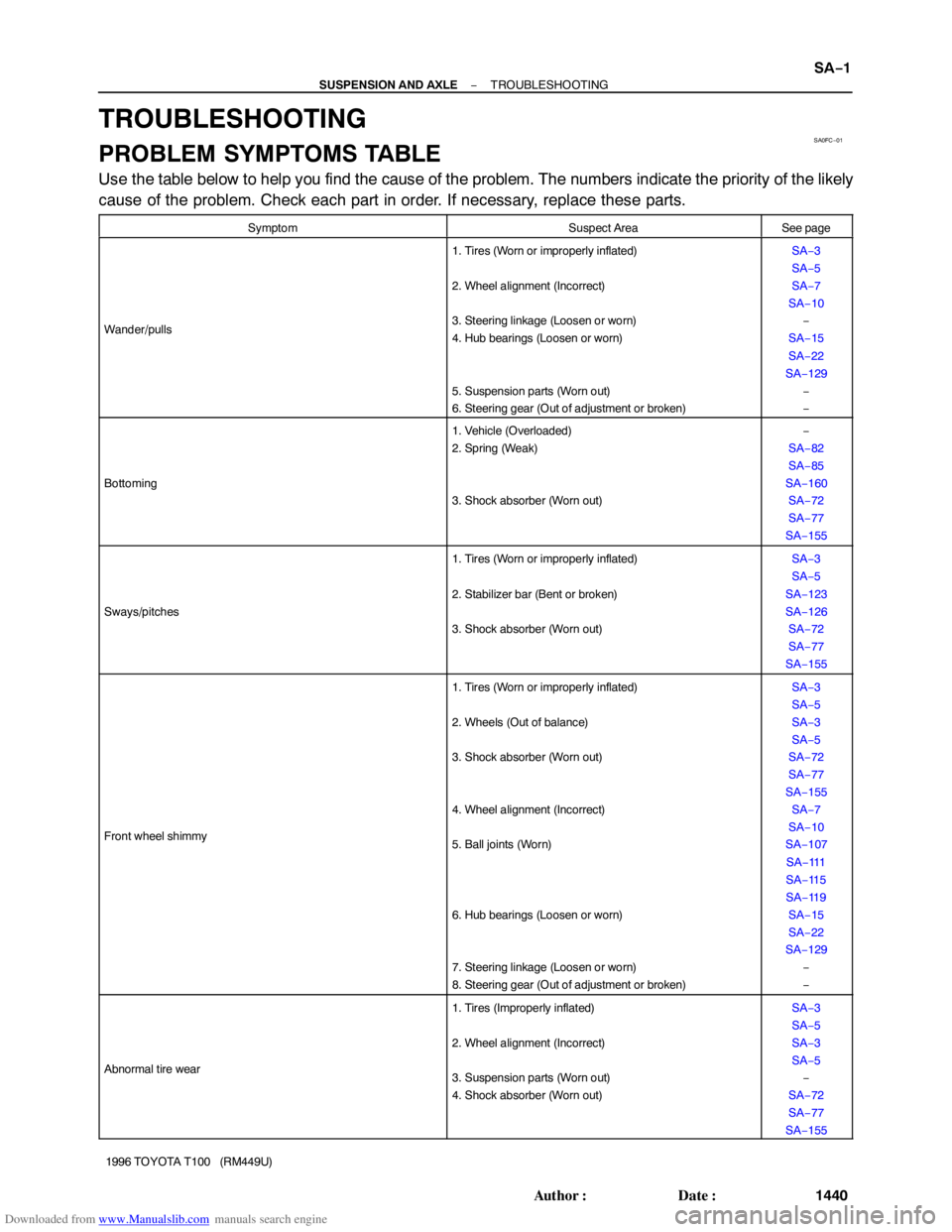
Downloaded from www.Manualslib.com manuals search engine SA0FC−01
− SUSPENSION AND AXLETROUBLESHOOTING
SA−1
1440 Author�: Date�:
1996 TOYOTA T100 (RM449U)
TROUBLESHOOTING
PROBLEM SYMPTOMS TABLE
Use the table below to help you find the cause of the problem. The numbers indicate the priority of the likely
cause of the problem. Check each part in order. If necessary, replace these parts.
SymptomSuspect AreaSee page
Wander/pulls
1. Tires (Worn or improperly inflated)
2. Wheel alignment (Incorrect)
3. Steering linkage (Loosen or worn)
4. Hub bearings (Loosen or worn)
5. Suspension parts (Worn out)
6. Steering gear (Out of adjustment or broken)SA−3
SA−5
SA−7
SA−10
−
SA−15
SA−22
SA−129
−
−
Bottoming
1. Vehicle (Overloaded)
2. Spring (Weak)
3. Shock absorber (Worn out)−
SA−82
SA−85
SA−160
SA−72
SA−77
SA−155
Sways/pitches
1. Tires (Worn or improperly inflated)
2. Stabilizer bar (Bent or broken)
3. Shock absorber (Worn out)SA−3
SA−5
SA−123
SA−126
SA−72
SA−77
SA−155
Front wheel shimmy
1. Tires (Worn or improperly inflated)
2. Wheels (Out of balance)
3. Shock absorber (Worn out)
4. Wheel alignment (Incorrect)
5. Ball joints (Worn)
6. Hub bearings (Loosen or worn)
7. Steering linkage (Loosen or worn)
8. Steering gear (Out of adjustment or broken)SA−3
SA−5
SA−3
SA−5
SA−72
SA−77
SA−155
SA−7
SA−10
SA−107
SA−11 1
SA−11 5
SA−11 9
SA−15
SA−22
SA−129
−
−
Abnormal tire wear
1. Tires (Improperly inflated)
2. Wheel alignment (Incorrect)
3. Suspension parts (Worn out)
4. Shock absorber (Worn out)SA−3
SA−5
SA−3
SA−5
−
SA−72
SA−77
SA−155
Page 1472 of 2062

Downloaded from www.Manualslib.com manuals search engine SA−2
− SUSPENSION AND AXLETROUBLESHOOTING
1441 Author�: Date�:
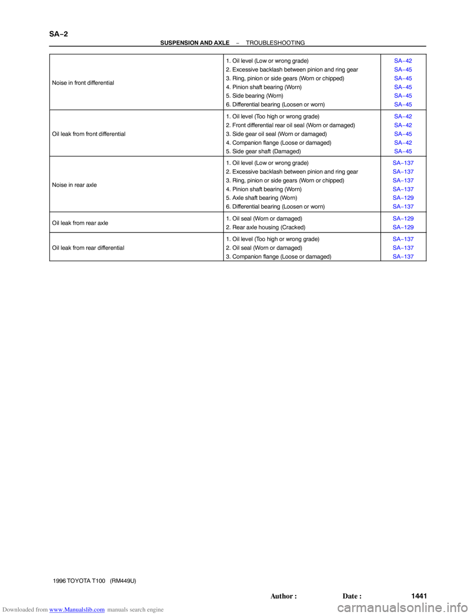
1996 TOYOTA T100 (RM449U) Noise in front differential
1. Oil level (Low or wrong grade)
2. Excessive backlash between pinion and ring gear
3. Ring, pinion or side gears (Worn or chipped)
4. Pinion shaft bearing (Worn)
5. Side bearing (Worn)
6. Differential bearing (Loosen or worn)SA−42
SA−45
SA−45
SA−45
SA−45
SA−45
Oil leak from front differential
1. Oil level (Too high or wrong grade)
2. Front differential rear oil seal (Worn or damaged)
3. Side gear oil seal (Worn or damaged)
4. Companion flange (Loose or damaged)
5. Side gear shaft (Damaged)SA−42
SA−42
SA−45
SA−42
SA−45
Noise in rear axle
1. Oil level (Low or wrong grade)
2. Excessive backlash between pinion and ring gear
3. Ring, pinion or side gears (Worn or chipped)
4. Pinion shaft bearing (Worn)
5. Axle shaft bearing (Worn)
6. Differential bearing (Loosen or worn)SA−137
SA−137
SA−137
SA−137
SA−129
SA−137
Oil leak from rear axle1. Oil seal (Worn or damaged)
2. Rear axle housing (Cracked)SA−129
SA−129
Oil leak from rear differential
1. Oil level (Too high or wrong grade)
2. Oil seal (Worn or damaged)
3. Companion flange (Loose or damaged)SA−137
SA−137
SA−137