Page 638 of 1354
ON
OFFShifting into
except D position
BE3840N14702I09121
ON
IG ON
D (−) (+)
− DIAGNOSTICSCRUISE CONTROL SYSTEM
DI−361
1996 RAV4 (RM447U)
2 Input signal check.
PREPARATION:
(a) See input signal check on page DI−328.
(b) Check the indicator light when shifting into except D posi-
tion.
OK:
The indicator light goes off when shifting into except
D position.
OK Proceed to next circuit inspection shown on
matrix chart (See page DI−336).
NG
3 Check voltage between terminal D of ECU connector and body ground.
PREPARATION:
Remove ECU with connectors still connected.
CHECK:
(a) Turn ignition switch ON.
(b) Measure voltage between terminal D of ECU connector
and body ground, when shifting into D position and other
positions.
OK:
Shift PositionVoltage
D position10 − 16 V
Other positionsBelow 1 V
OK Proceed to next circuit inspection shown on
matrix chart (See page DI−336).
NG
Page 641 of 1354
ON
OFFClutch pedal is depressed
BE3840N14702I09121
ON
IG ON
D (−) (+)
DI−364
− DIAGNOSTICSCRUISE CONTROL SYSTEM
1996 RAV4 (RM447U)
2 Input signal check.
CHECK:
(a) See input signal check on page DI−328.
(b) Check the indicator light when the clutch pedal is de-
pressed.
OK:
The indicator light goes off when the clutch pedal is
depressed.
OK Proceed to next circuit inspection shown on
matrix chart (See page DI−336).
NG
3 Check voltage between terminal D of ECU connector and body ground.
PREPARATION:
Remove ECU with connectors still connected.
CHECK:
(a) Turn ignition switch ON.
(b) Measure voltage between terminal D of ECU connector
and body ground, when the clutch pedal is depressed.
OK:
Shift PositionVoltage
ON (pedal depressed)Below 1 V
OFF10 − 16 V
OK Proceed to next circuit inspection shown on
matrix chart (See page DI−336).
NG
Page 651 of 1354
N17905
DLC1Cruise Control ECU
J9
Junction
Connector
13 W−L317
VA AV 8
Tc Tc
EB1IC1 W−L
BE3840N17427I09126
ON
DLC 1
E1
Tc (−)
(+)
DI−374
− DIAGNOSTICSCRUISE CONTROL SYSTEM
1996 RAV4 (RM447U)
Tc Circuit
CIRCUIT DESCRIPTION
This circuit sends a signal to the ECU that DTC output is required.
WIRING DIAGRAM
INSPECTION PROCEDURE
1 Check voltage between terminals Tc and E1 of DLC1.
CHECK:
(a) Turn ignition switch ON.
(b) Measure voltage between terminals Tc and E1 of DLC1.
OK:
Voltage: 10 − 16 V
NG Proceed to next circuit inspection shown on
matrix chart (See page DI−336).
OK
DI430−02
Page 786 of 1354

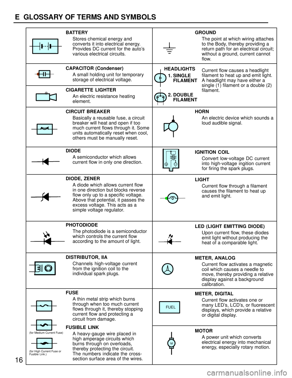
METER, ANALOG
Current flow activates a magnetic
coil which causes a needle to
move, thereby providing a relative
display against a background
calibration. LED (LIGHT EMITTING DIODE)
Upon current flow, these diodes
emit light without producing the
heat of a comparable light. IGNITION COIL
Convert low-voltage DC current
into high-voltage ingition current
for firing the spark plugs. 1. SINGLE
FILAMENT
GROUND
The point at which wiring attaches
to the Body, thereby providing a
return path for an electrical circuit;
without a ground, current cannot
flow.
Current flow causes a headlight
filament to heat up and emit light.
A headlight may have either a
single (1) filament or a double (2)
filament. BATTERY
Stores chemical energy and
converts it into electrical energy.
Provides DC current for the auto's
various electrical circuits.
CAPACITOR (Condenser)
A small holding unit for temporary
storage of electrical voltage.
CIRCUIT BREAKER
Basically a reusable fuse, a circuit
breaker will heat and open if too
much current flows through it. Some
units automatically reset when cool,
others must be manually reset.
DIODE
A semiconductor which allows
current flow in only one direction.
DIODE, ZENER
A diode which allows current flow
in one direction but blocks reverse
flow only up to a specific voltage.
Above that potential, it passes the
excess voltage. This acts as a
simple voltage regulator.
PHOTODIODE
The photodiode is a semiconductor
which controls the current flow
according to the amount of light.
FUSE
A thin metal strip which burns
through when too much current
flows through it, thereby stopping
current flow and protecting a
circuit from damage.
FUSIBLE LINK
A heavy-gauge wire placed in
high amperage circuits which
burns through on overloads,
thereby protecting the circuit.
The numbers indicate the cross-
section surface area of the wires.HORN
An electric device which sounds a
loud audible signal.
LIGHT
Current flow through a filament
causes the filament to heat up
and emit light.
METER, DIGITAL
Current flow activates one or
many LED's, LCD's, or fluorescent
displays, which provide a relative
or digital display.
MOTOR
A power unit which converts
electrical energy into mechanical
energy, especially rotary motion. CIGARETTE LIGHTER
An electric resistance heating
element.
DISTRIBUTOR, IIA
Channels high-voltage current
from the ignition coil to the
individual spark plugs.2. DOUBLE
FILAMENT HEADLIGHTS
FUEL
(for High Current Fuse or
Fusible Link.)
(for Medium Current Fuse)
M
16
E GLOSSARY OF TERMS AND SYMBOLS
Page 787 of 1354

17
E
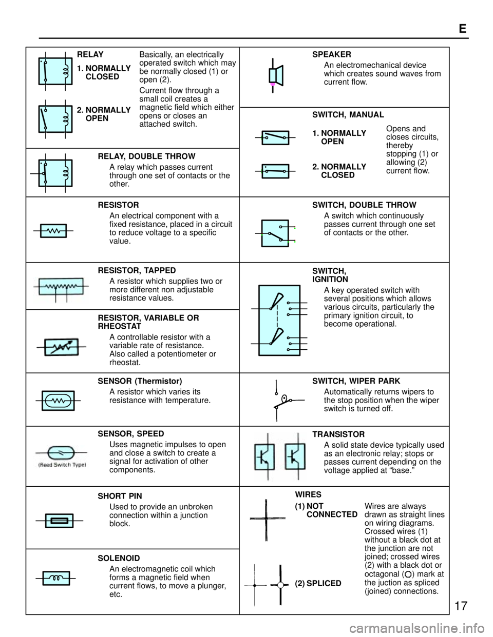
1. NORMALLY
OPENOpens and
closes circuits,
thereby
stopping (1) or
allowing (2)
current flow.
RESISTOR
An electrical component with a
fixed resistance, placed in a circuit
to reduce voltage to a specific
value.
RESISTOR, TAPPED
A resistor which supplies two or
more different non adjustable
resistance values.
SENSOR (Thermistor)
A resistor which varies its
resistance with temperature.
SHORT PIN
Used to provide an unbroken
connection within a junction
block.
SOLENOID
An electromagnetic coil which
forms a magnetic field when
current flows, to move a plunger,
etc.SWITCH, DOUBLE THROW
A switch which continuously
passes current through one set
of contacts or the other.
SWITCH,
IGNITION
A key operated switch with
several positions which allows
various circuits, particularly the
primary ignition circuit, to
become operational.
Wires are always
drawn as straight lines
on wiring diagrams.
Crossed wires (1)
without a black dot at
the junction are not
joined; crossed wires
(2) with a black dot or
octagonal (
) mark at
the juction as spliced
(joined) connections. RELAY, DOUBLE THROW
A relay which passes current
through one set of contacts or the
other.
SENSOR, SPEED
Uses magnetic impulses to open
and close a switch to create a
signal for activation of other
components.TRANSISTOR
A solid state device typically used
as an electronic relay; stops or
passes current depending on the
voltage applied at base.º SWITCH, WIPER PARK
Automatically returns wipers to
the stop position when the wiper
switch is turned off. SWITCH, MANUAL SPEAKER
An electromechanical device
which creates sound waves from
current flow.
2. NORMALLY
CLOSED
RESISTOR, VARIABLE OR
RHEOSTAT
A controllable resistor with a
variable rate of resistance.
Also called a potentiometer or
rheostat. 2. NORMALLY
OPEN RELAY
1. NORMALLY
CLOSEDBasically, an electrically
operated switch which may
be normally closed (1) or
open (2).
Current flow through a
small coil creates a
magnetic field which either
opens or closes an
attached switch.
(2) SPLICED WIRES
(1) NOT
CONNECTED
Page 798 of 1354
28
G ELECTRICAL WIRING ROUTING
Position of Parts in Engine Compartment
*1 : w/ A/C
*2 : w/o A/C
A 1 A/C Condenser Fan Motor E 1 Electronically Controlled Transmission Solenoid
A 2 A/C Magnetic Clutch and Lock Sensor E 2 Engine Coolant Temp. Sensor
A 3 A/C Triple Pressure SW (A/C Dual and Single
Pressure SW) F 1 Front Side Marker Light LH
A 4 A/C Water Temp. SW F 2 Front Side Marker Light RH
A 5 A/T Fluid Temp. SW F 3 Front Turn Signal Light LH and Front Parking
A 6 ABS Actuator Light LH
A 7 ABS Actuator F 4 Front Turn Signal Light RH and Front Parking
A 8 ABS Relay Light RH
A 9 ABS Relay F 5 Front Washer Motor
A 10 ABS Speed Sensor Front LH F 6 Front Wiper Motor
A 11 ABS Speed Sensor Front RH F 7 Fusible Link Block
B 1 Back-Up Light SW (M/T) G 1 Generator
B 2 Brake Fluid Level Warning SW G 2Generator
C 1 Center Diff. Lock Warning Buzzer SW H 1 Headlight LH
C 2 Crankshaft Position Sensor H 2 Headlight RH
C 3 Cruise Control Actuator H 3 Horn
D 1 Data Link Connector 1
Page 833 of 1354

64
ENGINE CONTROL
THE ENGINE CONTROL SYSTEM UTILIZES A MICROCOMPUTER AND MAINTAINS OVERALL CONTROL OF THE ENGINE ETC. AN
OUTLINE OF ENGINE CONTROL IS GIVEN HERE.
1. INPUT SIGNALS
(1) ENGINE COOLANT TEMP. SENSOR SIGNAL SYSTEM
THE ENGINE COOLANT TEMP. SENSOR DETECTS THE ENGINE COOLANT TEMP. AND HAS A BUILT-IN THERMISTOR WITH A
RESISTANCE WHICH VARIES ACCORDING TO THE ENGINE COOLANT TEMP. THUS THE ENGINE COOLANT TEMP. IS INPUT IN
THE FORM OF A CONTROL SIGNAL TO TERMINAL THW OF THE ENGINE CONTROL MODULE.
(2) INTAKE AIR TEMP. SIGNAL SYSTEM
THE INTAKE AIR TEMP. SENSOR DETECTS THE INTAKE AIR TEMP. , WHICH IS INPUT AS A CONTROL SIGNAL TO TERMINAL THA
OF THE ENGINE CONTROL MODULE.
(3) OXYGEN SENSOR SIGNAL SYSTEM
THE OXYGEN SENSOR DETECTS THE OXYGEN DENSITY IN THE EXHAUST EMISSION WHICH IS INPUT AS A CONTROL SIGNAL
TO TERMINALS OX1 AND OX2 OF THE ENGINE CONTROL MODULE.
(4) THROTTLE SIGNAL SYSTEM
THE THROTTLE POSITION SENSOR DETECTS THE THROTTLE VALVE OPENING ANGLE, WHICH IS INPUT AS A CONTROL
SIGNAL TO TERMINAL VTA OF THE ENGINE CONTROL MODULE, OR WHEN THE VALVE IS FULLY CLOSED.
(5) VEHICLE SPEED CIRCUIT
THE VEHICLE SPEED IS DETECTED BY VEHICLE SPEED SENSOR INSTALLED IN THE TRANSMISSION AND THE SIGNAL IS INPUT
TO TERMINAL SPD OF THE ENGINE CONTROL MODULE VIA THE COMBINATION METER.
(6) PARK/NEUTRAL POSITION SW SIGNAL SYSTEM
THE PARK/NEUTRAL POSITION SW DETECTS WHETHER THE SHIFT POSITION IS IN NEUTRAL OR NOT, AND INPUTS A CONTROL
SIGNAL TO TERMINAL NSW OF THE ENGINE CONTROL MODULE.
(7) A/C SW SIGNAL SYSTEM
THE OPERATING VOLTAGE OF THE A/C MAGNETIC CLUTCH IS DETECTED AND INPUT IN THE FORM OF A CONTROL SIGNAL TO
TERMINAL ACI OF THE ENGINE CONTROL MODULE.
(8) BATTERY SIGNAL SYSTEM
VOLTAGE IS CONSTANTLY APPLIED TO TERMINAL BATT OF THE ENGINE CONTROL MODULE. WHEN THE IGNITION SW IS
TURNED TO ON, VOLTAGE FOR THE ENGINE CONTROL MODULE OPERATION IS APPLIED VIA THE EFI MAIN RELAY TO
TERMINAL +B OF THE ENGINE CONTROL MODULE.
(9) INTAKE AIR VOLUME SIGNAL SYSTEM
INTAKE AIR VOLUME IS DETECTED BY THE MANIFOLD ABSOLUTE PRESSURE SENSOR AND IS INPUT AS A CONTROL SIGNAL
TO TERMINAL PIN OF THE ENGINE CONTROL MODULE.
(10) STARTER SIGNAL SYSTEM
TO CONFIRM THAT THE ENGINE IS CRANKING, THE VOLTAGE APPLIED TO THE STARTER MOTOR DURING CRANKING IS
DETECTED AND IS INPUT AS A CONTROL SIGNAL TO TERMINAL STA OF THE ENGINE CONTROL MODULE.
(11) ELECTRICAL LOAD SIGNAL SYSTEM
THE SIGNAL WHEN SYSTEMS SUCH AS THE REAR WINDOW DEFOGGER, HEADLIGHT, ETC. WHICH CAUSE A HIGH ELECTRICAL
BURDEN ARE ON IS INPUT TO TERMINAL ELS AS A CONTROL SIGNAL.
SYSTEM OUTLINE
Page 850 of 1354
81
TURN SIGNAL AND HAZARD WARNING LIGHT