Page 673 of 1354

P13988Spark Plug Side SST (A)
SST (B)
P13926
Magnetic
Finger
EM0494
P13989
SST (A)
SST (B)
− ENGINE MECHANICALVALVE CLEARANCE
EM−7
1996 RAV4 (RM447U)
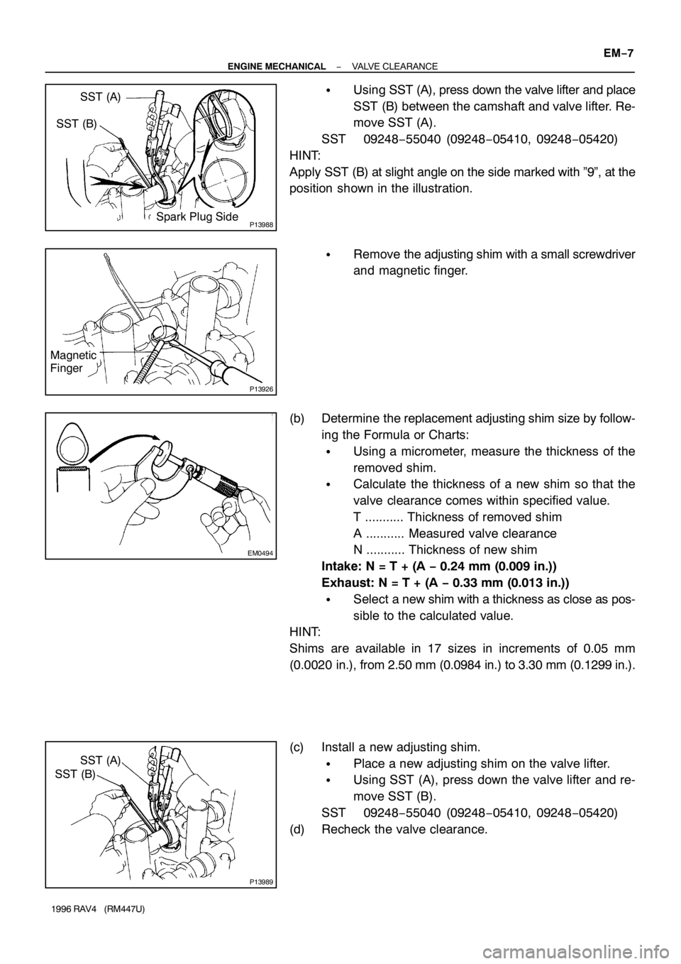
�Using SST (A), press down the valve lifter and place
SST (B) between the camshaft and valve lifter. Re-
move SST (A).
SST 09248−55040 (09248−05410, 09248−05420)
HINT:
Apply SST (B) at slight angle on the side marked with ”9”, at the
position shown in the illustration.
�Remove the adjusting shim with a small screwdriver
and magnetic finger.
(b) Determine the replacement adjusting shim size by follow-
ing the Formula or Charts:
�Using a micrometer, measure the thickness of the
removed shim.
�Calculate the thickness of a new shim so that the
valve clearance comes within specified value.
T ........... Thickness of removed shim
A ........... Measured valve clearance
N ........... Thickness of new shim
Intake: N = T + (A − 0.24 mm (0.009 in.))
Exhaust: N = T + (A − 0.33 mm (0.013 in.))
�Select a new shim with a thickness as close as pos-
sible to the calculated value.
HINT:
Shims are available in 17 sizes in increments of 0.05 mm
(0.0020 in.), from 2.50 mm (0.0984 in.) to 3.30 mm (0.1299 in.).
(c) Install a new adjusting shim.
�Place a new adjusting shim on the valve lifter.
�Using SST (A), press down the valve lifter and re-
move SST (B).
SST 09248−55040 (09248−05410, 09248−05420)
(d) Recheck the valve clearance.
Page 718 of 1354

EM1Q1−01
P13987
SST
SST
P03365
Both intake and exhaust
Bushing bore diameter
mm (in.)Bushing size
10.985 − 11.012
(0.4325 − 0.4335)Use STD
11.035 − 11.062
(0.4344 − 0.4355)Use O/S 0.05
P03156
Intake Exhaust
38.5 mm
(1.516 in.)40.5 mm
(1.594 in.)
S02337
SST
SST8.0 − 8.8
mm
8.0 − 8.8
mm Intake
Exhaust
EM−52
− ENGINE MECHANICALCYLINDER HEAD
1996 RAV4 (RM447U)
REPLACEMENT
REPLACE VALVE GUIDE BUSHINGS
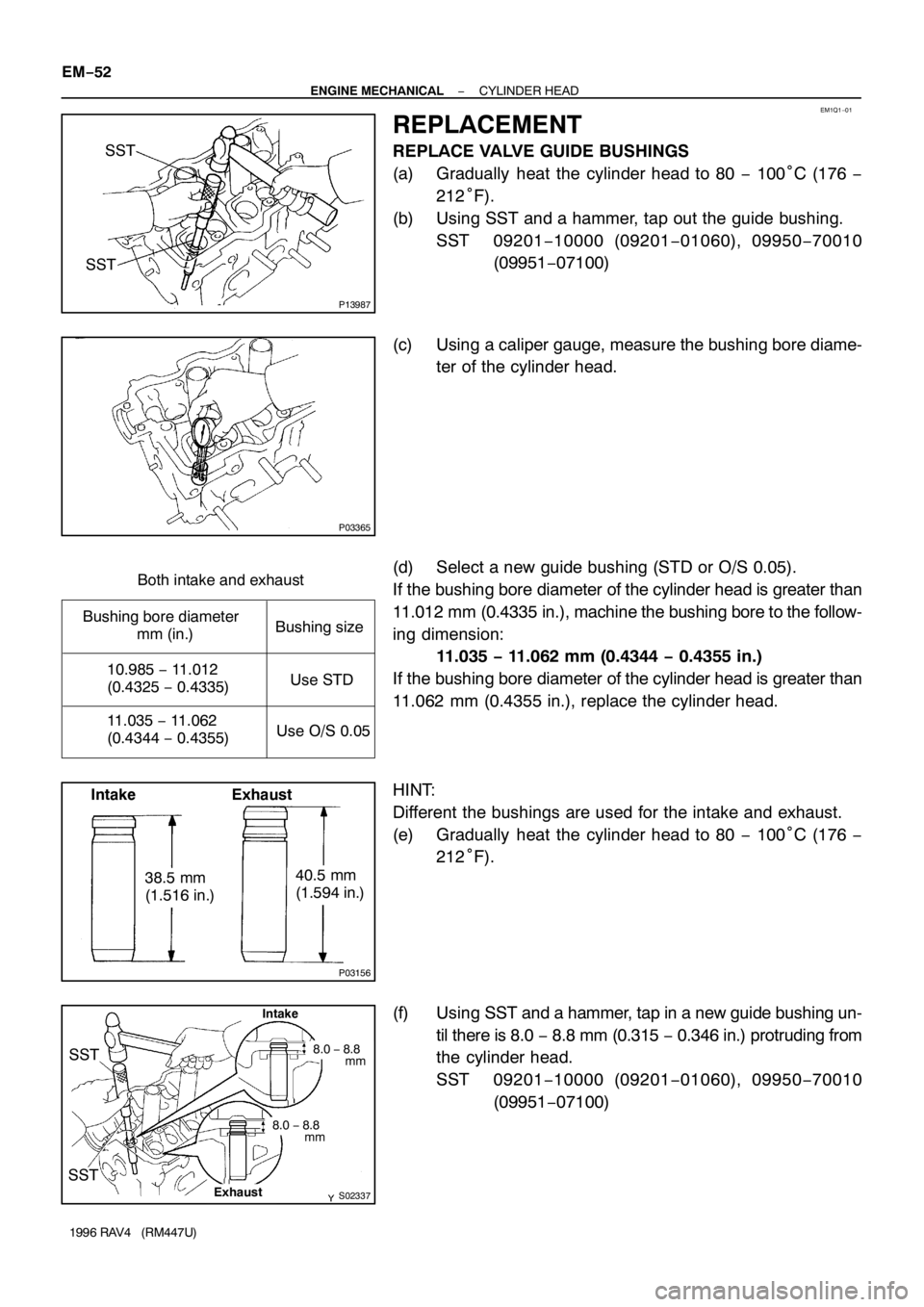
(a) Gradually heat the cylinder head to 80 − 100°C (176 −
212°F).
(b) Using SST and a hammer, tap out the guide bushing.
SST 09201−10000 (09201−01060), 09950−70010
(09951−07100)
(c) Using a caliper gauge, measure the bushing bore diame-
ter of the cylinder head.
(d) Select a new guide bushing (STD or O/S 0.05).
If the bushing bore diameter of the cylinder head is greater than
11.012 mm (0.4335 in.), machine the bushing bore to the follow-
ing dimension:
11.035 − 11.062 mm (0.4344 − 0.4355 in.)
If the bushing bore diameter of the cylinder head is greater than
11.062 mm (0.4355 in.), replace the cylinder head.
HINT:
Different the bushings are used for the intake and exhaust.
(e) Gradually heat the cylinder head to 80 − 100°C (176 −
212°F).
(f) Using SST and a hammer, tap in a new guide bushing un-
til there is 8.0 − 8.8 mm (0.315 − 0.346 in.) protruding from
the cylinder head.
SST 09201−10000 (09201−01060), 09950−70010
(09951−07100)
Page 762 of 1354
EM1Q2−01
EM1321
SST
EM7329
Oil Hole
P01038
EM1322
EM−96
− ENGINE MECHANICALCYLINDER BLOCK
1996 RAV4 (RM447U)
REPLACEMENT
1. REPLACE CONNECTING ROD BUSHINGS
(a) Using SST and a press, press out the bushing.
SST 09222−30010
(b) Align the oil holes of a new bushing and the connecting
rod.
(c) Using SST and a press, press in the bushing.
SST 09222−30010
(d) Using a pin hole grinder, hone the bushing to obtain the
standard specified clearance (See page EM−89) be-
tween the bushing and piston pin.
(e) Check the piston pin fit at normal room temperature. Coat
the piston pin with engine oil, and push it into the connect-
ing rod with your thumb.
2. REPLACE OVERSIZED (O/S) PISTONS FOR CYLIN-
DER BORING
HINT:
�Bore all the 4 cylinders for the O/S piston outside diame-
ter.
�Replace all the piston rings with ones to match the O/S
pistons.
(a) Keep 4 new O/S pistons.
O/S 0.50 piston diameter:
86.370 − 86.400 mm (3.4004 − 3.4016 in.)
Page 781 of 1354

11
C
FINDING A SHORT CIRCUIT
(a) Remove the blown fuse and disconnect all loads of the
fuse.
(b) Connect a test light in place of the fuse.
(c) Establish conditions in which the test light comes on.
Example:
- Ignition SW on
- Ignition SW and SW 1 on
- Ignition SW, SW 1 and Relay on (Connect the
Relay) and SW 2 off (or Disconnect SW 2)
(d) Disconnect and reconnect the connectors while
watching the test light.
The short lies between the connector where the test
light stays lit and the connector where the light goes
out.
(e) Find the exact location of the short by lightly shaking
the problem wire along the body.
CAUTION:
(a) Do not open the cover or the case of the ECU unless
absolutely necessary. (If the IC terminals are
touched, the IC may be destroyed by static
electricity.)
(b) When replacing the internal mechanism (ECU part)
of the digital meter, be careful that no part of your
body or clothing comes in contact with the
terminals of leads from the IC, etc. of the
replacement part (spare part).
DISCONNECTION OF MALE AND FEMALE
CONNECTORS
To pull apart the connectors, pull on the connector itself, not the
wire harness.
HINT: Check to see what kind of connector you are disconnecting
before pulling apart.
Page 977 of 1354

LU061−02
S01264
SST
LU0555
S01266
LU−2
− LUBRICATIONOIL AND FILTER
1996 RAV4 (RM447U)
REPLACEMENT
CAUTION:
�Prolonged and repeated contact with mineral oil will
result in the removal of natural fats from the skin,
leading to dryness, irritation and dermatitis. In addi-
tion, used engine oil contains potentially harmful
contaminants which may cause skin cancer.
�Care should be taken, therefore, when changing en-
gine oil to minimize the frequency and length of time
your skin is exposed to used engine oil. Protective
clothing and gloves that cannot be penetrated by oil
should be worn. The skin should be thoroughly
washed with soap and water, or use water−less hand
cleaner, to remove any used engine oil. Do not use
gasoline, thinners, or solvents.
�In order to preserve the environment, used oil and
used oil filters must be disposed of only at desig-
nated disposal sites.
1. DRAIN ENGINE OIL
(a) Remove the oil filler cap.
(b) Remove the oil drain plug, and drain the oil into a contain-
er.
2. REPLACE OIL FILTER
(a) Using SST, remove the oil filter.
SST 09228−06501
(b) Check and clean the oil filter installation surface.
(c) Lubricate the filter rubber gasket with clean engine oil.
(d) Lightly tighten the oil filter by hand until the rubber gasket
contacts the seat of the filter mounting.
Page 987 of 1354
LU066−02
P05373
P25628
SST LU−12
− LUBRICATIONOIL PUMP
1996 RAV4 (RM447U)
REPLACEMENT
1. REMOVE OIL SEAL
Using a screwdriver, pry out the oil seal.
2. INSTALL OIL SEAL
(a) Using SST and a hammer, tap in a new oil seal until its sur-
face is flush with the oil pump cover edge.
SST 09950−60010 (09951−00310),
09950−70010 (09951−07100)
(b) Apply MP grease to the oil seal lip.
3. REPLACE CRANKSHAFT FRONT OIL SEAL (See
page EM−96)
Page 1019 of 1354
Z00192
SST
MX0DU−01
Z00194
SST
Q08014
SST
Q05164
SST
Q00141
SST MX−24
− MANUAL TRANSAXLEMANUAL TRANSAXLE ASSEMBLY
1996 RAV4 (RM447U)
REPLACEMENT
1. REPLACE INPUT SHAFT BEARING AND OIL SEAL
(a) Remove the 3 bolts and transaxle case receiver.
(b) Using SST, pull out the bearing.
SST 09612−65014
(c) Using a screwdriver, remove the oil seal.
(d) Using SST, drive in a new oil seal.
SST 09608−00081, 09950−70010 (09951−07150)
(e) Coat the lip of seal with MP grease.
(f) Using SST, drive in a new bearing.
SST 09950−60010 (09951−00580), 09950−70010
(09951−07150)
(g) Install the transaxle case receiver.
(h) Install and torque the 3 bolts.
Torque: 7.4 N·m (75 kgf·cm, 65 in.·lbf)
(i) Using SST and a press, remove the inner race.
SST 09950−00020
(j) Using SST and a press, install a new input shaft front
bearing inner race.
SST 09316−60011 (09316−00021)
Page 1046 of 1354
Z00286
MX0DW−01
Z00288
SST
Z00289
Q06288
SST
− MANUAL TRANSAXLEDIFFERENTIAL CASE (2WD)
MX−51
1996 RAV4 (RM447U)
REPLACEMENT
1. Transmission Case Side:
REPLACE OIL SEAL AND TAPERED ROLLER BEAR-
ING OUTER RACE
(a) Using a screwdriver, remove the oil seal.
(b) Remove the oil baffle.
(c) Using a brass bar and hammer, drive out the bearing out-
er race lightly and evenly.
(d) Remove the shim.
(e) Install the shim (See page MX−49).
HINT:
First select and install a shim of lesser thickness than before.
(f) Using SST and a press, install a new tapered roller bear-
ing outer race.
SST 09316−60011 (09316−00011, 09316−00041)
(g) Install the oil baffle.
HINT:
Install the oil baffle projection into the case side cutout.
(h) Using SST and a hammer, drive in a new oil seal.
SST 09223−15020, 09950−70010 (09951−07150)
(i) Coat the lip of oil seal with MP grease.