Page 278 of 1354
CL04F−03
− CLUTCHTROUBLESHOOTING
CL−1
1996 RAV4 (RM447U)
TROUBLESHOOTING
PROBLEM SYMPTOMS TABLE
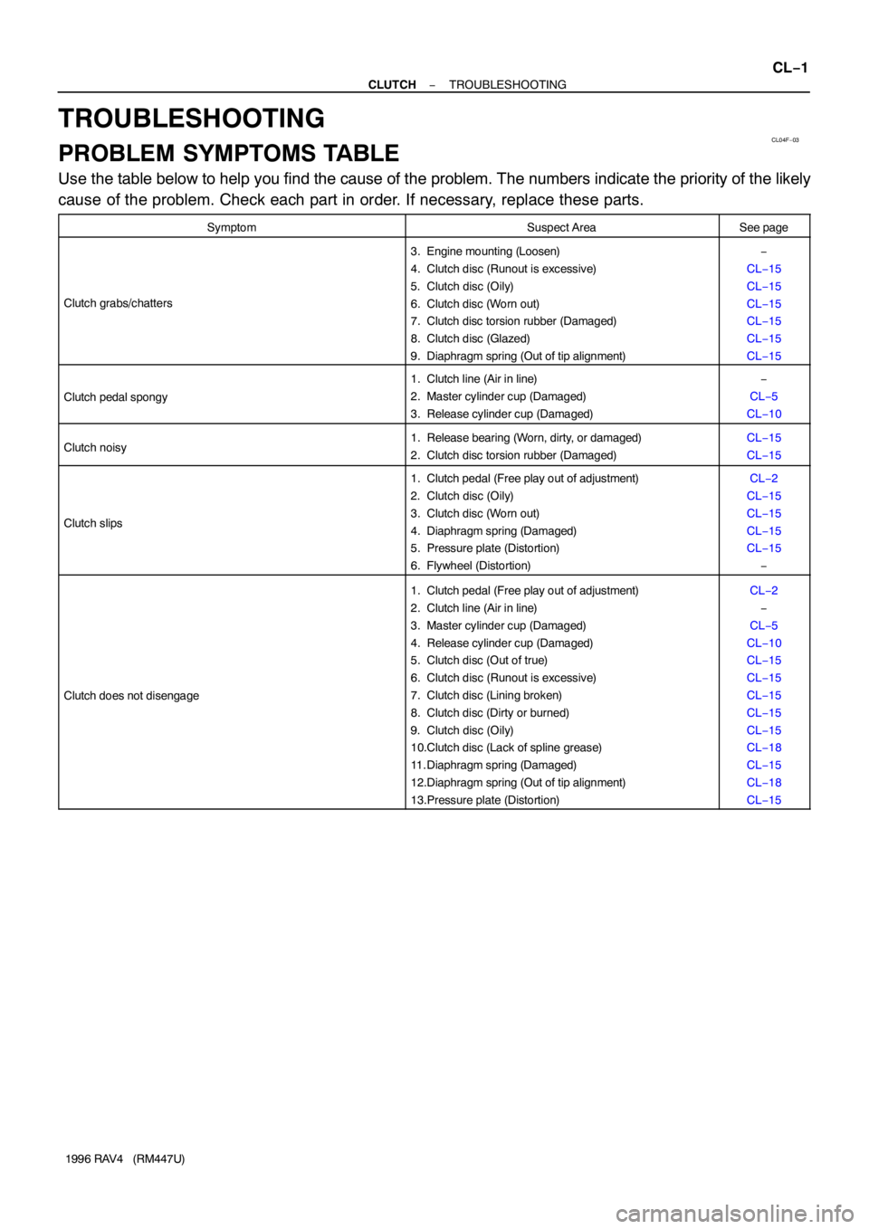
Use the table below to help you find the cause of the problem. The numbers indicate the priority of the likely
cause of the problem. Check each part in order. If necessary, replace these parts.
SymptomSuspect AreaSee page
Clutch grabs/chatters
3. Engine mounting (Loosen)
4. Clutch disc (Runout is excessive)
5. Clutch disc (Oily)
6. Clutch disc (Worn out)
7. Clutch disc torsion rubber (Damaged)
8. Clutch disc (Glazed)
9. Diaphragm spring (Out of tip alignment)−
CL−15
CL−15
CL−15
CL−15
CL−15
CL−15
Clutch pedal spongy
1. Clutch line (Air in line)
2. Master cylinder cup (Damaged)
3. Release cylinder cup (Damaged)−
CL−5
CL−10
Clutch noisy1. Release bearing (Worn, dirty, or damaged)
2. Clutch disc torsion rubber (Damaged)CL−15
CL−15
Clutch slips
1. Clutch pedal (Free play out of adjustment)
2. Clutch disc (Oily)
3. Clutch disc (Worn out)
4. Diaphragm spring (Damaged)
5. Pressure plate (Distortion)
6. Flywheel (Distortion)CL−2
CL−15
CL−15
CL−15
CL−15
−
Clutch does not disengage
1. Clutch pedal (Free play out of adjustment)
2. Clutch line (Air in line)
3. Master cylinder cup (Damaged)
4. Release cylinder cup (Damaged)
5. Clutch disc (Out of true)
6. Clutch disc (Runout is excessive)
7. Clutch disc (Lining broken)
8. Clutch disc (Dirty or burned)
9. Clutch disc (Oily)
10.Clutch disc (Lack of spline grease)
11. Diaphragm spring (Damaged)
12.Diaphragm spring (Out of tip alignment)
13.Pressure plate (Distortion)CL−2
−
CL−5
CL−10
CL−15
CL−15
CL−15
CL−15
CL−15
CL−18
CL−15
CL−18
CL−15
Page 279 of 1354

Q08873
Push Rod Play
Adjust Point
Pedal Height
Adjust Point
Push Rod
Play
Pedal HeightCL04G−02
CL0042
Pedal Freeplay
CL0512
25 mm (0.98 in.) or more
Release Point
Full Stroke
End Position CL−2
− CLUTCHCLUTCH PEDAL
1996 RAV4 (RM447U)
CLUTCH PEDAL
INSPECTION
1. CHECK PEDAL HEIGHT IS CORRECT
Pedal height from asphalt sheet:
157.6 − 167.6 mm (6.205 − 6.598 in.)
2. IF NECESSARY, ADJUST PEDAL HEIGHT
Loosen the lock nut and turn the stopper bolt until the height is
correct. Tighten the lock nut.
3. CHECK PEDAL FREEPLAY AND PUSH ROD PLAY
(a) Push in on the pedal until the beginning of clutch resis-
tance is felt.
Pedal freeplay: 5.0−15.0 mm (0.197−0.591 in.)
(b) Gently push on the pedal until the resistance begins to in-
crease a little.
Push rod play at pedal top:
1.0−5.0 mm (0.039−0.197 in.)
4. IF NECESSARY, ADJUST PEDAL FREEPLAY AND
PUSH ROD PLAY
(a) Loosen the lock nut and turn the push rod until the free-
play and push rod play are correct.
(b) Tighten the lock nut.
(c) After adjusting the pedal freeplay, check the pedal height.
(d) Connect the air duct and install the lower finish panel.
5. INSPECT CLUTCH RELEASE POINT
(a) Pull the parking brake lever and install wheel stopper.
(b) Start the engine and idle the engine.
(c) Without depressing the clutch pedal, slowly shift the shift
lever into the reverse position until the gears contact.
(d) Gradually depress the clutch pedal and measure the
stroke distance from the point the gear noise stops (re-
lease point) up to the full stroke end position.
Standard distance:
25 mm (0.98 in.) or more
(From pedal stroke end position to release point)
If the distance is not as specified.
�Inspect pedal height.
�Inspect push rod play and pedal freeplay.
�Bleed the clutch line.
�Inspect the clutch cover and disc.
Page 292 of 1354
CL04R−02
Q08882
Flywheel
N·m (kgf·cm, ft·lbf): Specified torqueClutch Cover
Release Fork
BootRelease Fork Support Release Bearing with Hub x6 Clutch Disc
19 (195, 14)
47 (480, 35)88 (900, 65)
− CLUTCHCLUTCH UNIT
CL−15
1996 RAV4 (RM447U)
CLUTCH UNIT
COMPONENTS
Page 293 of 1354
CL04S−02
Q06030
Matchmarks
Q06031
CL−16
− CLUTCHCLUTCH UNIT
1996 RAV4 (RM447U)
REMOVAL
1. REMOVE TRANSAXLE FROM ENGINE
(2WD: See page MX−2)
(4WD: See page MX−8)
2. REMOVE CLUTCH COVER AND DISC
(a) Place matchmarks on the flywheel and clutch cover.
(b) Loosen each set bolt one turn at a time until spring tension
is released.
(c) Remove the set bolts, and pull off the clutch cover with the
clutch disc.
NOTICE:
Do not drop the clutch disc.
3. REMOVE RELEASE BEARING AND FORK FROM
TRANSAXLE
(a) Remove the release bearing together with the fork and
then separate them.
(b) Remove the boot.
Page 294 of 1354

CL04T−01
Q06032
Q06033
Q06034
Q06035
AB
Q06036
− CLUTCHCLUTCH UNIT
CL−17
1996 RAV4 (RM447U)
INSPECTION
1. INSPECT CLUTCH DISC FOR WEAR OR DAMAGE
Using calipers, measure the rivet head depth.
Minimum rivet depth: 0.3 mm (0.012in.)
If a problem is found, replace the clutch disc.
2. INSPECT CLUTCH DISC RUNOUT
Using a dial indicator, check the disc runout.
Maximum runout: 0.8 mm (0.031 in.)
If runout is excessive, replace the clutch disc.
3. INSPECT FLYWHEEL RUNOUT
Using a dial indicator, check the flywheel runout.
Maximum runout: 0.1 mm (0.004 in.)
If runout is excessive, replace the flywheel.
Torque: 88 N·m (900 kgf·cm, 65 ft·lbf)
4. INSPECT DIAPHRAGM SPRING FOR WEAR
Using calipers, measure the diaphragm spring for depth and
width of wear.
Maximum:
A (Depth): 0.5 mm (0.020 in.)
B (Width): 6.0 mm (0.236 in.)
If necessary, replace the clutch cover.
5. INSPECT RELEASE BEARING
Turn the bearing by hand while applying force in the axial direc-
tion.
HINT:
The bearing is permanently lubricated and requires no cleaning
or lubrication.
If a problem is found, replace the bearing.
Page 295 of 1354

CL04U−02
Q06037
Flywheel
Side
SST
Q06038
Matchmarks8 2, 5
6
SST
3
7 1, 4
Q06039SST
Q06245
CL−18
− CLUTCHCLUTCH UNIT
1996 RAV4 (RM447U)
INSTALLATION
1. INSTALL CLUTCH DISC AND CLUTCH COVER ON
FLYWHEEL
(a) Insert SST in the clutch disc, and then set them and the
clutch cover in position.
SST 09301−00220
(b) Align the matchmarks on the clutch cover and flywheel.
(c) Temporarily tighten the topmost bolt from the 3 near the
knock pins.
HINT:
Temporarily tighten the No.3 bolt.
(d) Torque the bolts on the clutch cover in the order shown.
Torque: 19 N·m (195 kgf·cm, 14 ft·lbf)
2. CHECK DIAPHRAGM SPRING TIP ALIGNMENT
Using a dial indicator with roller instrument, check the dia-
phragm spring tip alignment.
Maximum non−alignment: 0.5 mm (0.020 in.)
If alignment is not as specified, using SST, adjust the dia-
phragm spring tip alignment.
SST 09333−00013
3. APPLY MOLYBDENUM DISULPHIDE LITHIUM BASE
GREASE (NLGI NO.2)
(a) Apply release hub grease to the following parts.
�Release fork and hub contact point
�Release fork and push rod contact point
�Release fork pivot point
(b) Apply clutch spline grease.
�Clutch disc spline
HINT:
Recommended grease part number 08887−01706 (100g).
4. INSTALL RELEASE BEARING AND FORK TO TRANS-
AXLE
Install the bearing to the release fork, and then install them to
the transaxle.
5. INSTALL TRANSAXLE TO ENGINE
(2WD: See page MX−2)
(4WD: See page MX−8)
Page 339 of 1354

− DIAGNOSTICSENGINE
DI−19
1996 RAV4 (RM447U) FC (E6−14) − E1 (E4−14)
G−R ↔ BRIG switch ON9 ∼ 14
EGR (E4−23) − E1 (E4−14)B−W ↔ BRIG switch ON0 ∼ 3
ISCC (E4−9) − E1 (E4−14)B−Y ↔ BRIG switch ON
Disconnect E4 of ECM connector9 ∼ 14
ISCO (E4−10) − E1 (E4−14)B−L ↔ BRIG switch ON
Disconnect E4 of ECM connector9 ∼ 14
OX1 (E5−6) − E1 (E4−14)B ↔ BRMaintain engine speed at 2,500 rpm for 2 mins. after
warning up.Pulse generation
OX2 (E5−5) − E1 (E4−14)B ↔ BRMaintain engine speed at 2,500 rpm for 2 mins. after
warning up.Pulse generation
KNK (E5−10) − E1 (E4−14)B ↔ BRIdlingPulse generation
(See page DI−56)
* NSW (E6−22) − E1 (E4−14)B−W ↔ BR
IG switch ON
Other shift position in ”P” , ”N” position9 ∼ 14
IG switch ON
Shift position in ”P” , ”N” position0 ∼ 3.0
SPD (E6−9) − E1 (E4−14)V−W ↔ BRIG switch ON
Rotate driver wheel slowly.Pulse generation
(See page DI−94)
TE1 (E5−15) − E1 (E4−14)L−W ↔ BRIG switch ON9 ∼ 14
W (E6−5) − E1 (E4−14)G−R ↔ BRIdling9 ∼ 14
IG switch ONBelow 3.0
AC (E6−10) − E1 (E4−14)Y−G ↔ BRIdling, A/C switch ONBelow 2.0
Idling, A/C switch OFF9 ∼ 14
ACT (E6−21) − E1 (E4−14)R−Y ↔ BRIdling, A/C switch ON9 ∼ 14
Idling, A/C switch OFFBelow 2.0
* OD2 (E6−7) − E1 (E4−14)LG ↔ BRIG switch ON, O/D main switch pushed out9 ∼ 14
IG switch ON, O/D main switch pushed in0 ∼ 3
* OD1 (E6−20) − E1 (E4−14)Y−B ↔ BRIG switch ON, Cruise control ECU no request O/D cut9 ∼ 14
IG switch ON, Cruise control ECU request O/D cut0 ∼ 3
EVP (E4−22) − E1 (E4−14)P ↔ BRIG switch ON9 ∼ 14
TPC (E5−8) − E1 (E4−14)R−W ↔ BRIG switch ON9 ∼ 14
PTNK (E5−7) − E2 (E5−9)L−Y ↔ BR
IG switch ON, Disconnect vacuum hose from vapor
pressure sensor2.9 ∼ 3.7
Apply vacuum
(4.0 kPa, 30 mmHg, 1.18 in. Hg)
(less than 66.7 kPa, 500 mmHg, 19.7 in. Hg)
Below 0.5
ELS (E6−17) − E1 (E4−14)B ↔ BRDefogger switch and taillight switch ON7.5 ∼ 14
Defogger switch and taillight switch OFF0 ∼ 1.5
SDL (E6−16) − E1 (E4−14)W ↔ BRDuring transmissionPules generation
*: A/T only
Page 416 of 1354
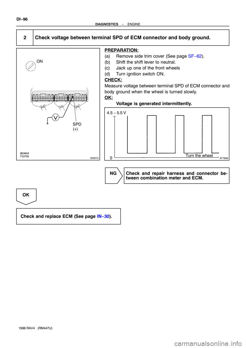
A00415
SPD
(+)
ON
AT7809
4.5 − 5.5 V
Turn the wheel
0
DI−96
− DIAGNOSTICSENGINE
1996 RAV4 (RM447U)
2 Check voltage between terminal SPD of ECM connector and body ground.
PREPARATION:
(a) Remove side trim cover (See page SF−62).
(b) Shift the shift lever to neutral.
(c) Jack up one of the front wheels
(d) Turn ignition switch ON.
CHECK:
Measure voltage between terminal SPD of ECM connector and
body ground when the wheel is turned slowly.
OK:
Voltage is generated intermittently.
NG Check and repair harness and connector be-
tween combination meter and ECM.
OK
Check and replace ECM (See page IN−30).