Page 193 of 1354
F04193
SST
SST
BR03I−02
BR−34
− BRAKEPROPORTIONING VALVE (P VALVE)
1996 RAV4 (RM447U)
PROPORTIONING VALVE (P VALVE)
ON−VEHICLE INSPECTION
1. INSTALL LSPV GAUGE (SST) AND BLEED AIR
SST 09709−29018
2. RAISE MASTER CYLINDER PRESSURE AND CHECK REAR WHEEL CYLINDER PRESSURE
Master cylinder pressureRear wheel cylinder pressure
2,452 kPa (25 kgf/cm2, 356 psi)2,452 kPa (25 kgf/cm2, 356 psi)
7,845 kPa (80 kgf/cm2, 1,138 psi)3,800 kPa (38.75 kgf/cm2, 551 psi)
When inspecting the fluid pressure, inspect the left front and right rear together, and the right front and left
rear together.
If the rear wheel cylinder pressure is incorrect, replace the P valve assembly.
3. BLEED BRAKE SYSTEM (See page BR−4)
4. CHECK FOR LEAKS
Page 195 of 1354

BR1811
R00326
R00324
R00325
BR1813
BR−36
− BRAKEABS ACTUATOR
1996 RAV4 (RM447U)
(c) Place the ”SHEET A” (SST) on the actuator checker.
SST 09990−00163
4. INSPECT BRAKE ACTUATOR OPERATION OF
FRONT RH WHEEL
(a) Start the engine, and run it at idle.
(b) Turn the selector switch of the actuator checker to
”FRONT RH” position.
(c) Push and hold in the MOTOR switch for a few seconds.
Make sure that you can hear the motor running.
(d) Depress the brake pedal and hold it for about 15 seconds,
and check that the brake pedal does not go down.
(e) With your foot still applying onto the brake pedal, push
MOTOR switch and check that the pedal does not pul-
sate.
(f) Depress the brake pedal and hold it. As you hold the ped-
al down, push and hold in the POWER SWITCH for a few
seconds. Check that the pedal does not go down.
NOTICE:
Do not keep the POWER SWITCH pushed for more than 10
seconds.
(g) With your foot still applying onto the brake pedal, release
the POWER SWITCH and check that the pedal goes
down.
(h) With your foot still applying onto the brake pedal, push the
MOTOR switch and check that the brake pedal returns.
(i) Release the brake pedal.
5. INSPECT FRONT LH WHEEL
(a) Turn the selector switch to ”REAR RH” position.
(b) Repeating (c) to (i) in the step 4, check the actuator oper-
ating similarly.
6. INSPECT REAR RH WHEEL
(a) Turn the selector switch to ”FRONT LH” position.
(b) Repeating (c) to (i) in the step 4, check the actuator opera-
tion similarly.
Page 196 of 1354
BR1811
− BRAKEABS ACTUATOR
BR−37
1996 RAV4 (RM447U)
7. INSPECT REAR LH WHEEL
Repeating (c) to (i) in the step 4, check the actuator operation
similarly.
HINT:
When inspecting the ”REAR LH” position, push the REAR LH
switch instead of the POWER SWITCH. This makes it possible
to inspect wherever the selector switch position indicates.
8. PUSH MOTOR SWITCH
(a) Push and hold in the MOTOR switch for a few seconds.
(b) Stop the engine.
9. DISCONNECT ACTUATOR CHECKER (SST) FROM
ACTUATOR
Remove the ”SHEET A” (SST) and disconnect the actuator
checker (SST) and sub−wire harness (SST) from the actuator,
control relay and body side wire harness.
SST 09990−00150, 09990−00163, 09990−00200,
09990−00300
10. CONNECT CONNECTORS
(a) Connect the connector to the actuator.
(b) Connect the 2 connectors to the control relay.
11. CLEAR DTC (See page DI−234)
Page 209 of 1354
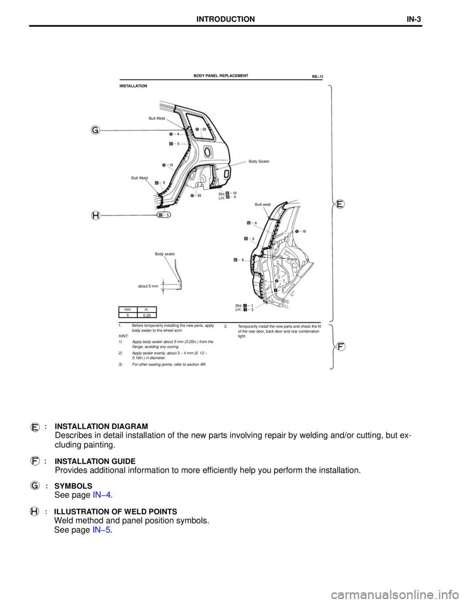
mm in.
5
0.20
1. Before temporarily installing the new parts, apply
body sealer to the wheel arch.
HINT:
1) Apply body sealer about 5 mm (0.20in.) from the
flange, avoiding any oozing.
2) Apply sealer evenly, about 3 - 4 mm (0. 12 -
0.16in.) in diameter.
3) For other sealing points, refer to section AR.
SYMBOLS
See page IN-4.
RH:
LH: BODY PANEL REPLACEMENT
RE-11
INSTALLATION
Butt Weld
Body Sealer
Butt Weld
Butt weld
Body sealer
Braze
about 5 mm
RH:
LH:
2. Temporarily install the new parts and check the fit
of the rear door, back door and rear combination
light.
INSTALLATION DIAGRAM
Describes in detail installation of the new parts involving repair by welding and/or cutting, but exœ
cluding painting.
INSTALLATION GUIDE
Provides additional information to more efficiently help you perform the installation.
ILLUSTRATION OF WELD POINTS
Weld method and panel position symbols.
See page IN-5.
INTRODUCTIONINœ3
Page 212 of 1354
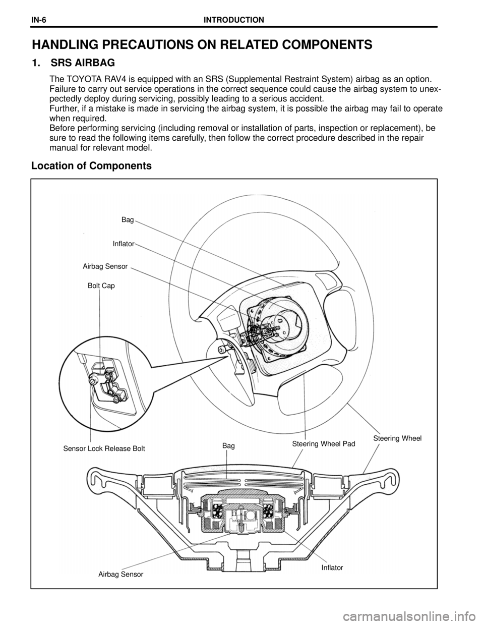
Airbag SensorInflator Sensor Lock Release BoltBagSteering Wheel PadSteering Wheel Bolt Cap Airbag SensorInflatorBag
HANDLING PRECAUTIONS ON RELATED COMPONENTS
1. SRS AIRBAG
The TOYOTA RAV4 is equipped with an SRS (Supplemental Restraint System) airbag as an option.
Failure to carry out service operations in the correct sequence could cause the airbag system to unexœ
pectedly deploy during servicing, possibly leading to a serious accident.
Further, if a mistake is made in servicing the airbag system, it is possible the airbag may fail to operate
when required.
Before performing servicing (including removal or installation of parts, inspection or replacement), be
sure to read the following items carefully, then follow the correct procedure described in the repair
manual for relevant model.
Location of Components
INTRODUCTIONINœ6
Page 213 of 1354

Component to be alignedSection of repair manual
for relevant model
Front Wheels
Suspension and Axle (SA) section
Rear Wheels
Suspension and Axle (SA) section
1. Never disassemble the steering wheel pad assembly.
2. Do not subject the steering wheel pad to shocks or bring magnets close to it.
3. Do not expose the steering wheel pad to high temperatures or fire.
4. If grease, cleaner, oil or water gets on the steering wheel pad, promptly wipe it off with a dry cloth.
5. Do not drop the steering wheel pad. Never use a steering wheel pad which has been dropped.
6. Never install the steering wheel and pad in another vehicle.
7. When the steering wheel pad is removed, store it on a stable, flat place with the pad surface facing upœ
wards. Never place anything on top of the pad.
8. When work on the vehicle will produce too strong a shock, first loosen the sensor lock release bolt until
it turns freely and perform the work after sensor lock occurs.
9. Even in cases where the vehicle is in a low-impact accident where the airbag is not activated, always
check the pad surface and airbag sensor part. If dents, cracks or deformation is visible, replace the airœ
bag with a new assembly.
10. When disposing of the vehicle or steering wheel, always deploy the airbag first.
11. The deployed inflator inside the steering wheel pad is hot, so dispose of it after it has been cooled by
atmospheric air. Never apply water to cool it down.
2. BRAKE SYSTEM
The brake system is one of the most important safety components. Always follow the directions and
notes given in section BR of the repair manual for the relevant model year when handling brake system
parts.
3. DRIVE TRAIN AND CHASSIS
The drive train and chassis are components that can have great effects on the running performance
and vibration resistance of the vehicle. After installing components in the sections listed in the table
below, perform alignments to ensure correct mounting angles and dimensions. Particularly accurate
repair of the body must also be done to ensure correct alignment.
HINT: Correct procedures and special tools are required for alignment. Always follow the directions
given in the repair manual for the relevant model during alignment and section DI of this manual.
INTRODUCTIONINœ7
Page 219 of 1354
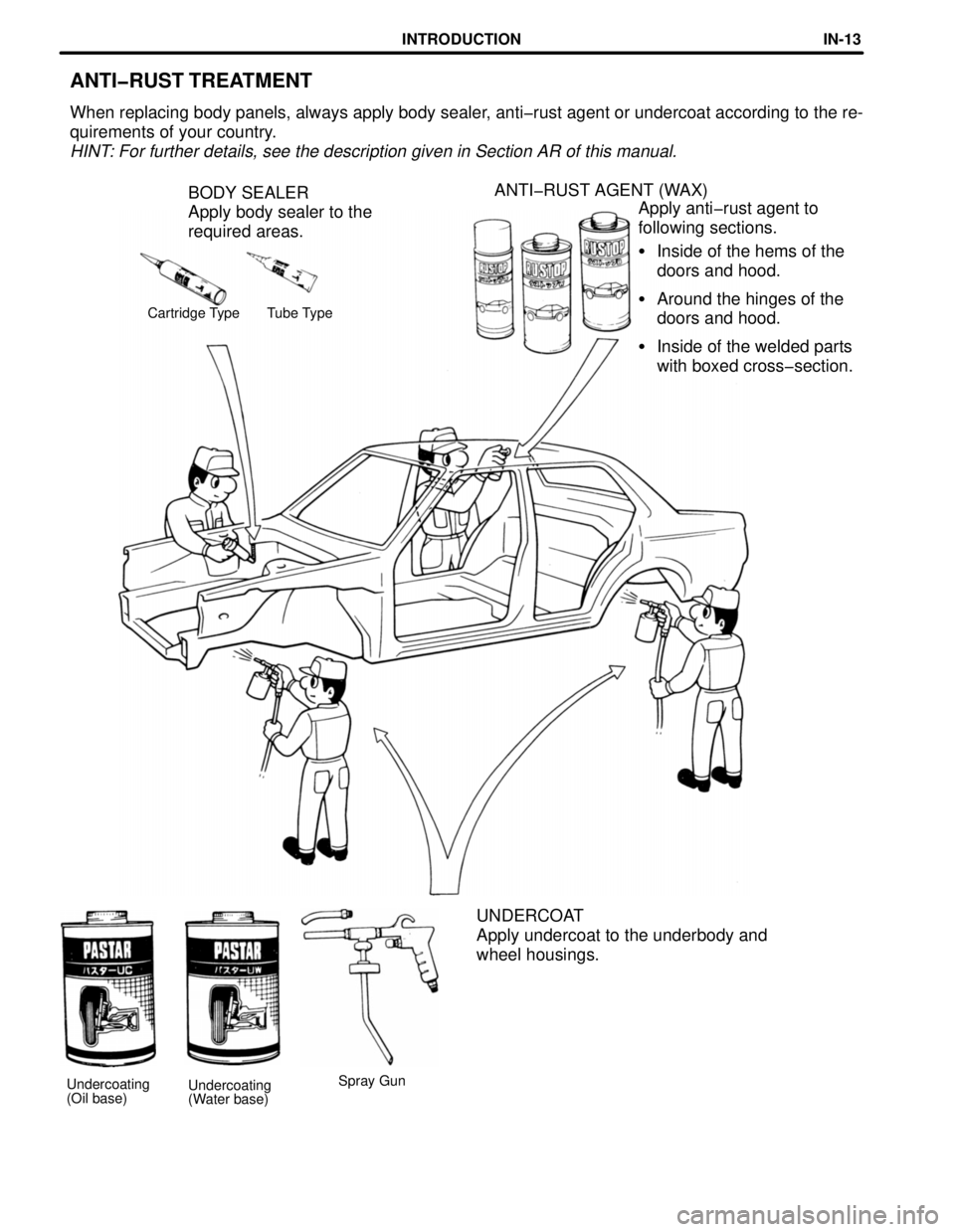
ANTI-RUST TREATMENT
When replacing body panels, always apply body sealer, anti-rust agent or undercoat according to the reœ
quirements of your country.
HINT: For further details, see the description given in Section AR of this manual.
BODY SEALER
Apply body sealer to the
required areas.ANTI-RUST AGENT (WAX)
Apply anti-rust agent to
following sections.
�Inside of the hems of the
doors and hood.
�Around the hinges of the
doors and hood.
�Inside of the welded parts
with boxed cross-section.
Cartridge Type Tube Type
UNDERCOAT
Apply undercoat to the underbody and
wheel housings.
Spray Gun
Undercoating
(Oil base)Undercoating
(Water base)
INTRODUCTIONINœ13
Page 221 of 1354
ABS Antilock Brake System
A/C Air Conditioner
assy assembly
ECT Electronic Controlled Transmission
ECU Electronic Control Unit
e.g. Exempli Gratia (for Example)
Ex. Except
FWD Front Wheel Drive Vehicles
4WD Four Wheel Drive Vehicles
in. inch
LH Left-hand
LHD Left-hand Drive
MIG Metal Inert Gas
M/Y Model Year
PPS Progressive Power Steering
RH Right-hand
RHD Right-hand Drive
SRS Supplemental Restraint System
w/ with
w/o without
ABBREVIATIONS USED IN THIS MANUAL
For convenience, the following abbreviations are used in this
manual.
INTRODUCTIONINœ15