Page 1268 of 1354
SF0RG−02
S01838
2WD
SST
P01630
Ohmmeter
− SFIKNOCK SENSOR
SF−57
1996 RAV4 (RM447U)
INSPECTION
1. 4WD:
REMOVE ENGINE AND TRANSAXLE ASSEMBLY (See
page EM−68)
2. REMOVE KNOCK SENSOR
(a) Disconnect the knock sensor connector.
(b) Using SST, remove the knock sensor.
SST 09816−30010
Torque: 44 N·m (450 kgf·cm, 33 ft·lbf)
3. INSPECT KNOCK SENSOR
Using an ohmmeter, check that there is no continuity between
the terminal and body.
If there is continuity, replace the sensor.
4. REINSTALL KNOCK SENSOR
Installation is in the reverse order of removal.
5. 4WD:
REINSTALL ENGINE AND TRANSAXLE ASSEMBLY
(See page EM−74)
Page 1283 of 1354
R06184
SR0FI−02
R09732
− STEERINGSTEERING WHEEL
SR−9
1996 RAV4 (RM447U)
STEERING WHEEL
INSPECTION
1. CHECK STEERING WHEEL FREEPLAY
With the vehicle stopped and tires facing straight ahead, rock
the steering wheel gently back and forth with light finger pres-
sure.
Freeplay should not exceed the maximum.
Maximum freeplay: 30 mm (1.18 in.)
2. CHECK STEERING EFFORT
(a) Center the steering wheel.
(b) Remove the steering wheel pad (See page SR−12).
(c) Start the engine and run it at idle.
(d) Measure the steering effort in both directions.
Reference: 5.9 N·m (60 kgf·cm, 52 in.·lbf)
HINT:
Be sure to consider the tire type, pressure and contact surface
before making your diagnosis.
(e) Torque the steering wheel set nut.
Torque: 34 N·m (350 kgf·cm, 25 ft·lbf)
(f) Install the steering wheel pad (See page SR−19).
Page 1293 of 1354
SR0F5−03
W02018
− STEERINGNON−TILT STEERING COLUMN
SR−19
1996 RAV4 (RM447U)
INSTALLATION
1. Tilt Steering Column:
CONNECT SLIDING YOKE
(a) Align the matchmarks on the main shaft and sliding yoke,
and connect them.
(b) Torque the bolt.
Torque: 35 N·m (360 kgf·cm, 26 ft·lbf)
2. Non−Tilt Steering Column:
INSTALL STEERING COLUMN ASSEMBLY
(a) Temporarily tighten the 2 column assembly set bolts and
2 nuts.
(b) Connect the connectors.
3. Tilt Steering Column:
INSTALL STEERING COLUMN ASSEMBLY
(a) Torque the 2 column assembly set bolts and 2 nuts.
Torque: 25 N·m (260 kgf·cm, 19 ft·lbf)
(b) Connect the connectors.
4. INSTALL STEERING COLUMN PROTECTOR
Torque the bolt.
Torque: 5.0 N·m (50 kgf·cm, 44 in.·lbf)
Page 1294 of 1354

5. Non−Tilt Steering Column:
INSTALL NO.2 INTERMEDIATE S")
W02017
Non−tilt Steering Column :
Tilt−Steering Column :
MatchmarksBA
SR−20
− STEERINGNON−TILT STEERING COLUMN
1996 RAV4 (RM447U)
5. Non−Tilt Steering Column:
INSTALL NO.2 INTERMEDIATE SHAFT
(a) Connect the No.2 intermediate shaft to the main shaft.
(b) Temporarily tighten the bolt A.
6. Tilt Steering Column:
INSTALL No.2 INTERMEDIATE SHAFT
(a) Connect the No.2 intermediate shaft to the sliding yoke.
(b) Temporarily tighten the bolt A.
7. CONNECT NO.2 INTERMEDIATE SHAFT
(a) Align the matchmarks on the No.2 intermediate shaft and
control valve shaft, and connect them.
(b) Torque the bolt B.
Torque: 35 N·m (360 kgf·cm, 26 ft·lbf)
(c) Torque the bolt A.
Torque: 35 N·m (360 kgf·cm, 26 ft·lbf)
8. INSTALL SPIRAL CABLE (See page BE−14)
9. INSTALL COMBINATION SWITCH WITH SPIRAL
CABLE
(a) Tighten the 3 screws.
(b) Connect the connectors.
(c) Connect the airbag connector.
10. INSTALL NO.2 HEATER TO REGISTER DUCT
11. Non−Tilt Steering Column:
INSTALL UPPER AND LOWER COLUMN COVERS
(a) Install the protector to the lower cover and tighten the 3
screws.
(b) Tighten the 3 screws.
(c) Torque the 2 column assembly set bolts and 2 nuts.
Torque: 25 N·m (260 kgf·cm, 19 ft·lbf)
12. Tilt Steering Column:
INSTALL UPPER AND LOWER COLUMN COVERS
(a) Install the protector to the lower cover and tighten the 3
screws.
(b) Tighten the 3 screws.
13. INSTALL INSTRUMENT PANEL LOWER INSERT
Tighten the 3 screws.
14. INSTALL LOWER FINISH PANEL
(a) Tighten the 2 panel set bolts.
(b) Connect the hood lock control lever with the 2 screws.
15. CENTER SPIRAL CABLE
(a) Check that the front wheels are facing straight ahead.
(b) Turn the cable counterclockwise until it locks.
(c) Then rotate the cable clockwise about 2.5 turns to left of
the center.
HINT:
The spiral cable rotates approx. 5 turns maximum.
Page 1295 of 1354
− STEERINGNON−TILT STEERING COLUMN
SR−21
1996 RAV4 (RM447U)
16. INSTALL STEERING WHEEL
(a) Align the matchmarks on the wheel and steering main
shaft assembly.
(b) Torque the wheel set nut.
Torque: 34 N·m (350 kgf·cm, 25 ft·lbf)
(c) Connect the airbag connector.
17. INSTALL STEERING WHEEL PAD
NOTICE:
�Make sure that the pad is installed to the specified
torque.
�If the pad has been dropped, or there are cracks,
dents or other defects in the case or connector, re-
place the wheel pad with a new one.
�When installing the pad, take care that the wiring
does not interfere with other parts and is not pinched
between other parts.
(a) Connect the airbag connector.
(b) Install the pad after confirming that the circumference
groove of the torx screws are caught on the screw case.
(c) Using a torx socket wrench, torque the 2 screws.
Torque: 8.8 N·m (90 kgf·cm, 78 in.·lbf)
(d) Install the steering wheel lower No.2 and No.3 covers.
18. CHECK STEERING WHEEL CENTER POINT
Page 1303 of 1354

(d) Using SST, compress the compression spring.
SST 09950−40010 (09958−04010)
NOTICE:
Do not bend the universal join")
W01124
SST
W01117
− STEERINGTILT STEERING COLUMN
SR−29
1996 RAV4 (RM447U)
(d) Using SST, compress the compression spring.
SST 09950−40010 (09958−04010)
NOTICE:
Do not bend the universal joint of the shaft more than 20°.
(e) Using a snap ring expander, install a new snap ring to the
shaft.
4. INSTALL TILT LEVER RETAINER
NOTICE:
Make sure to install the retainer facing the correct direction
(See page SR−22).
5. INSTALL STEERING COLUMN UPPER TUBE WITH
STEERING MAIN SHAFT
(a) Install the upper tube with the shaft to the steering column
tube.
(b) Using a hexagon wrench, torque the 2 tilt steering bolts.
Torque: 20 N·m (204 kgf·cm, 15 ft·lbf)
(c) Check that the upper tube turns smoothly.
6. INSTALL COMBINATION SWITCH BRACKET
Torque the 2 bracket set bolts.
Torque: 6.0 N·m (58 kgf·cm, 53 in.·lbf)
7. INSTALL 3 TENSION SPRINGS
HINT:
Install the springs with the tilt function at maximum tilt up.
8. INSTALL STEERING COLUMN UPPER BRACKET
AND STEERING COLUMN UPPER CLAMP
(See page SR−18)
9. CHECK TILT STEERING OPERATION
Page 1305 of 1354
SR0FV−02
Z19806
Union Bolt
PS Gear Assembly
Tube ClampPressure Feed Tube
Return Hose
Vacuum Hose
13 (130, 9)
44 (450, 32)
*36 (365, 26)
52 (525, 38)
29 (300, 22)
3 Door vehicle 64 (650, 47)
5 Door vehicle 113 (1,150, 83)
43 (440, 32)
113 (1, 150, 83)
x7
x6
13 (130, 9)
� Gasket
N·m (kgf·cm, ft·lbf)Bracket
BushingDrive Belt
PS Vane Pump Assembly
with Pump Bracket
62 (630, 46)
29 (300, 22)
BushingBracket
� Gasket
Clamp
(A/T)
Front Exhaust Pipe
� Gasket Stabilizer Bar
with Link
Front Suspension
Crossmember Assembly
137 (1, 400, 101)
206 (2, 100, 152)
127 (1, 300, 94)
Engine Under
Cover
127 (1, 300, 94)
137 (1, 400, 101)
112 (1, 140, 82)
8.3 (84, 73 in.·lbf)
48 (490, 35)
�
206 (2, 100, 152)
: Specified torque
* For use with SST � Non−reusable part
W02019
3 Door vehicle 64 (650, 47)
5 Door vehicle 113 (1,150, 83)
− STEERINGPOWER STEERING VANE PUMP
SR−31
1996 RAV4 (RM447U)
POWER STEERING VANE PUMP
COMPONENTS
Page 1306 of 1354
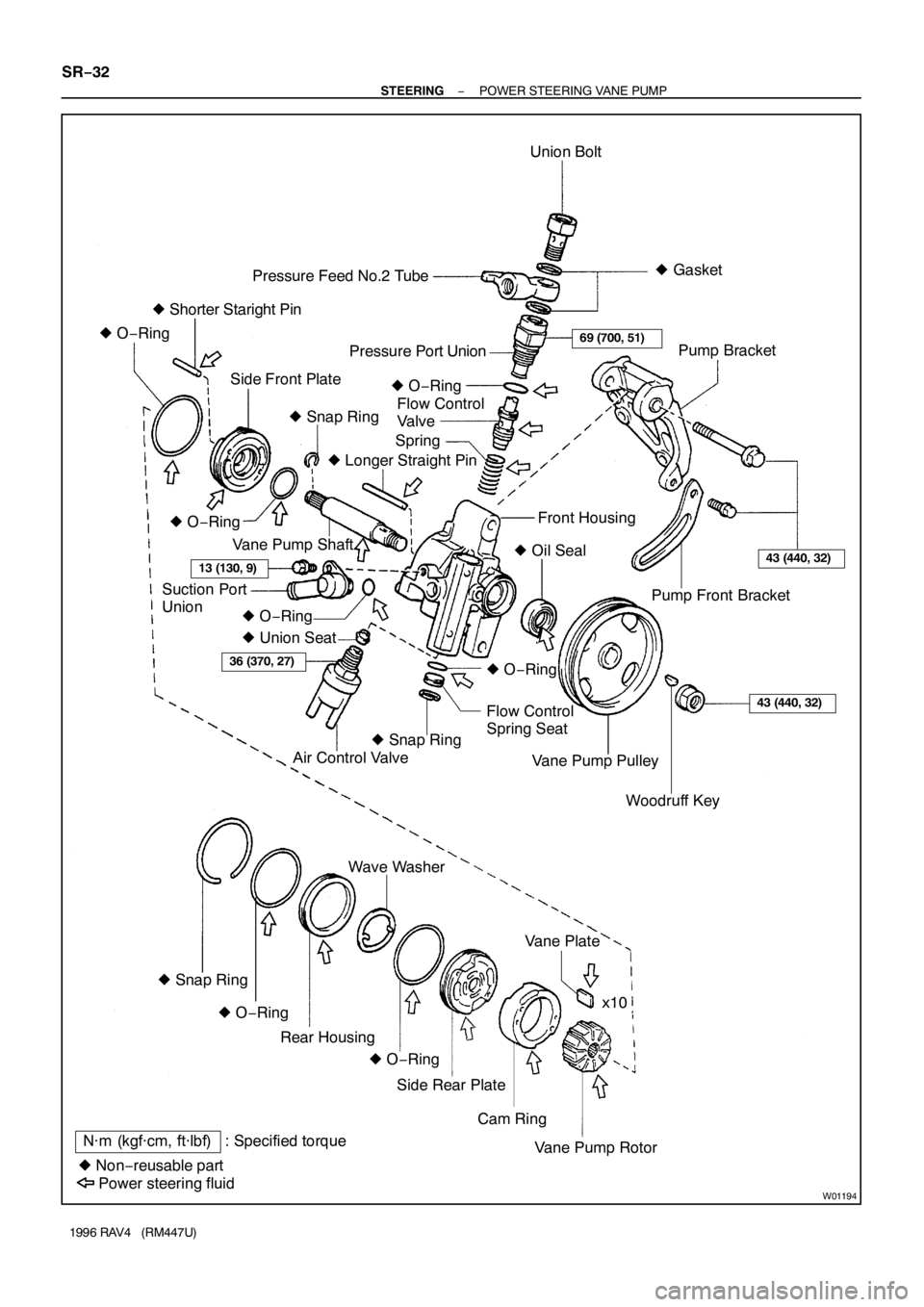
W01194
N·m (kgf·cm, ft·lbf) : Specified torque
� Non−reusable partUnion Bolt
Spring Pressure Feed No.2 Tube
Side Front PlatePressure Port Union
Flow Control
Valve
Pump Front Bracket
Flow Control
Spring Seat� Gasket
� Shorter Staright Pin
Air Control Valve � O−Ring
� Snap Ring� O−Ring
� Union Seat� Longer Straight Pin
Vane Pump Shaft
Suction Port
UnionFront Housing
� O−Ring
� Oil Seal
� O−Ring
� O−Ring
Woodruff Key Vane Pump PulleyPump Bracket
� Snap Ring
Cam Ring Side Rear PlateVane Plate Wave Washer
Vane Pump Rotorx10
Power steering fluidRear Housing
� O−Ring � O−Ring � Snap Ring
69 (700, 51)
13 (130, 9)43 (440, 32)
36 (370, 27)
43 (440, 32)
SR−32
− STEERINGPOWER STEERING VANE PUMP
1996 RAV4 (RM447U)

INSPECTION
1. 4WD:
REMOVE ENGINE AND TRANSAXLE ASSEMBLY (See
page EM−68)
2. REMOVE KNOCK SENSOR
(a) Disconn")

STEERING WHEEL
INSPECTION
1. CHECK STEERING WHEEL FREEPLAY
With the vehicle stopped and tires facing straight ahead, roc")

INSTALLATION
1. Tilt Steering Column:
CONNECT SLIDING YOKE
(a) Align the matchmarks on the main shaft and sliding")

16. INSTALL STEERING WHEEL
(a) Align the matchmarks on the wheel and steering main
shaft assembly.
(b) Torque the wheel set nut.
Tor")

44 (450, 32)
*36 (365, 26)
52 (525, 38)
29 (300, 22)
3 Door vehicle 64 (650, 47)
5 Door")