Page 1222 of 1354
SF0Q6−01
S01937
3 Door Vehicles
LH Rear Seat Assembly5 Door Vehicles
LH Rear Seat Assembly
37 (375, 27)
37 (375, 27)
Rear Seat Hinge Cover
Floor Service Hole Cover
29 (300, 22)
Fuel Pump & Sender
Gauge Connector
� Gasket
Fuel Suction w/ Pump &
Gauge AssemblyFuel Return
Vent Hose� Gasket
Fuel Outlet Pipe
x 8
� GasketFuel Hose
Fuel Pump Connector
Ground Strap
Fuel Pump
Fuel Pump Filter
Rubber Cushion � Clip Fuel Pump Clamp
N·m (kgf·cm, ft·lbf) : Specified torque
� Non−reusable part SF−8
− SFIFUEL PUMP
1996 RAV4 (RM447U)
COMPONENTS
Page 1223 of 1354

(b)
S01829
− SFIFUEL PUMP
SF−9
1996 RAV4 (RM447U)
REMOVAL
CAUTION:
Do not smoke or work near an open flame when working on
the fuel pump.
1. REMOVE LH REAR SEAT ASSEMBLY
2.")
SF0Q7−02
S01828(a)
(b)
S01829
− SFIFUEL PUMP
SF−9
1996 RAV4 (RM447U)
REMOVAL
CAUTION:
Do not smoke or work near an open flame when working on
the fuel pump.
1. REMOVE LH REAR SEAT ASSEMBLY
2. REMOVE FLOOR SERVICE HOLE COVER
(a) Take out the floor carpet.
(b) Remove the 4 screws and service hole cover.
HINT:
At the time of installation, plaese refer to the following items.
Check for fuel leakage (See page SF−1).
3. DISCONNECT FUEL PUMP & SENDER GAUGE CON-
NECTOR
4. DISCONNECT FUEL PIPE AND HOSE FROM FUEL
SUCTION TUBE
CAUTION:
Remove the fuel filler cap to prevent the fuel from flowing
out.
(a) Remove the union bolt and 2 gaskets, and disconnect the
outlet pipe from the suction tube.
HINT:
At the time of installation, plaese refer to the following items.
Install the outlet pipe with 2 new gaskets and bolt.
Torque: 29 N·m (300 kgf·cm, 22 ft·lbf)
(b) Disconnect the return vent hose from the suction tube.
5. REMOVE FUEL SUCTION w/ PUMP & GAUGE TUBE
ASSEMBLY
(a) Remove the 8 bolts.
Torque: 3.5 N·m (35 kgf·cm, 31 in.·lbf)
(b) Pull out the suction w/ pump & gauge tube assembly.
NOTICE:
Do not damage the fuel pump filter. Be careful that the arm
of the sender gauge should not bent.
(c) Remove the gasket from the set plate.
HINT:
At the time of installation, plaese refer to the following items.
Install a new gasket to the set plate.
Page 1227 of 1354
SF0QB−01
S01959
3 Door Vehicles
LH Rear Seat Assembly5 Door Vehicles
LH Rear Seat Assembly
37 (375, 27)
37 (375, 27)
Rear Seat Hinge Cover
Floor Service Hole Cover
29 (300, 22)
Fuel Pump & Sender
Gauge Connector
� Gasket
Fuel Suction w/ Pump &
Gauge Tube AssemblyFuel Return
Vent Hose� Gasket
Fuel Outlet Pipe
x 8
� GasketFuel Hose
Fuel Pressure Regulator � O−Ring Fuel Filter
N·m (kgf·cm, ft·lbf) : Specified torque
� Non−reusable partClip
− SFIFUEL PRESSURE REGULATOR
SF−13
1996 RAV4 (RM447U)
FUEL PRESSURE REGULATOR
COMPONENTS
Page 1235 of 1354
SST
(Hose)SST
(Clamp)
Injector Fuel Filter
(On−Vehicle)SST
(Union)
S01833
Union Bolt
SST
(Hose)
Fuel FilterSST
(Union)
Gasket
P25498
SST
(Hose)
SST
(Clamp) SS")
SF0QJ−04
S01900
Union Bolt
SST (Union)SST
(Hose)SST
(Clamp)
Injector Fuel Filter
(On−Vehicle)SST
(Union)
S01833
Union Bolt
SST
(Hose)
Fuel FilterSST
(Union)
Gasket
P25498
SST
(Hose)
SST
(Clamp) SST
(Union)
O−Ring
Vinyl
Tube
S01354
TOYOTA
Hand−Held Tester
− SFIINJECTOR
SF−21
1996 RAV4 (RM447U)
INSPECTION
1. INSPECT INJECTOR INJECTION
CAUTION:
Keep injector clear of sparks during the test.
(a) Connect SST (union and hose) to the fuel filter outlet with
the 2 gaskets and union bolt.
SST 09268−41046 (90405−09015)
Torque: 29 N·m (300 kgf·cm, 22 ft·lbf)
HINT:
Use the vehicle’s fuel filter.
(b) Install the grommet and O−ring to the injector.
(c) Connect SST (union and hose) to the injector, and hold
the injector and union with SST (clamp).
SST 09268−41046
(d) Put the injector into a graduated cylinder.
HINT:
Install a suitable vinyl hose onto the injector to prevent gasoline
from splashing out.
(e) Connect the TOYOTA hand−held tester to the DLC3.
(f) Turn the ignition switch ON and TOYOTA hand−held tes-
ter main switch ON.
NOTICE:
Do not start the engine.
(g) Select the active test mode on the TOYOTA hand−held
tester.
(h) Please refer to the TOYOTA hand−held tester operator’s
manual for further details.
(i) If you have no TOYOTA hand−held tester, connect the
positive (+) and negative (−) leads from the battery to the
fuel pump connector (See page SF−5).
Page 1238 of 1354
S01941
S01953
Install
Air Hose
S01948
No.1
No.2
No.3
No.4
Gray
Brown SF−24
− SFIINJECTOR
1996 RAV4 (RM447U)
(f) Tighten the 2 bolts holding the delivery pipe to the cylinder
head.
Torque: 13 N·m (130 kgf·cm, 9 ft·lbf)
(g) Install the air hose for the air assist system to the intake
manifold port.
(h) Connect the fuel inlet hose to the fuel filter with 2 new gas-
kets and the union bolt.
Torque: 29 N·m (300 kgf·cm, 22 ft·lbf)
3. INSTALL ENGINE COMPARTMENT R/B NO.2
4. INSTALL EGR VALVE AND PIPE
HINT:
Place a new gasket on the intake manifold.
Torque:
Nut:
13 N·m (130 kgf·cm, 9 ft·lbf)
Union nut:
59 N·m (600 kgf·cm, 43 ft·lbf)
5. CONNECT ENGINE WIRE TO INTAKE MANIFOLD
HINT:
The No.1 and No.3 injector connectors are brown, and the No.2
and No.4 injector connectors are gray.
6. CONNECT THROTTLE BODY TO INTAKE MANIFOLD
7. INSTALL CYLINDER HEAD COVER (See page EM−55
)
8. INSTALL AIR CLEANER ASSEMBLY
9. INSTALL DISTORIBUTOR (See page IG−13)
Page 1239 of 1354
SF0QM−02
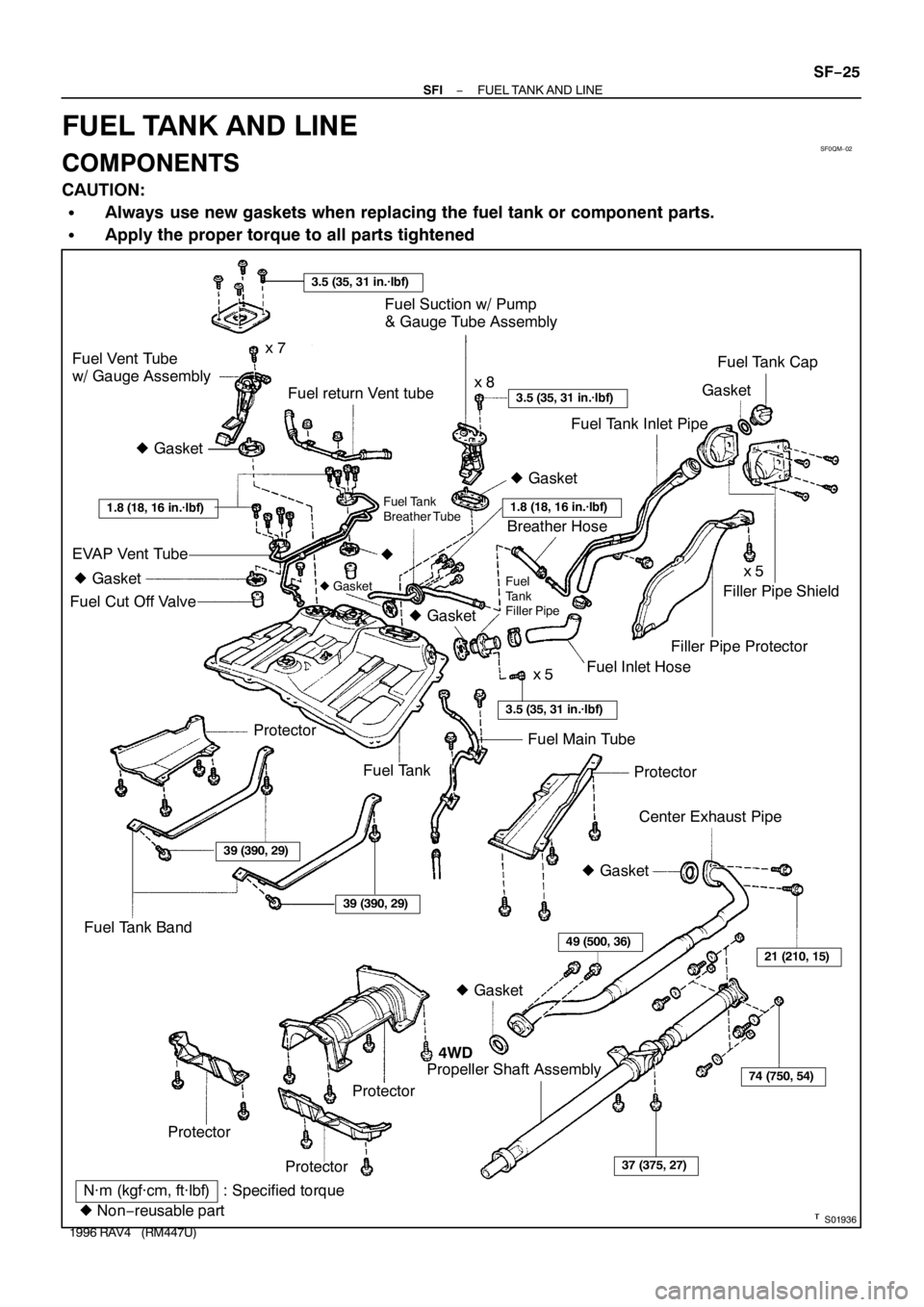
3.5 (35, 31 in.·lbf)
S01936
Fuel Vent Tube
w/ Gauge Assembly
Fuel return Vent tubeFuel Suction w/ Pump
& Gauge Tube Assembly
Fuel Tank Inlet PipeGasketFuel Tank Cap
3.5 (35, 31 in.·lbf)
� Gasket
1.8 (18, 16 in.·lbf)1.8 (18, 16 in.·lbf)
� Gasket
� Gasket� Gasket
� Gasket
EVAP Vent Tube
Fuel Cut Off Valvex 7
x 8
x 5
x 5
3.5 (35, 31 in.·lbf)
�
Fuel Tank
Breather Tube
Breather Hose
Fuel
Tank
Filler Pipe
Fuel Inlet HoseFiller Pipe ProtectorFiller Pipe Shield
Fuel Main Tube
Protector Fuel Tank Protector
Center Exhaust Pipe
� Gasket
Fuel Tank Band
39 (390, 29)
39 (390, 29)
� Gasket
49 (500, 36)21 (210, 15)
74 (750, 54)
37 (375, 27)
Propeller Shaft Assembly4WD
Protector
ProtectorProtector
N·m (kgf·cm, ft·lbf): Specified torque
� Non−reusable part
− SFIFUEL TANK AND LINE
SF−25
1996 RAV4 (RM447U)
FUEL TANK AND LINE
COMPONENTS
CAUTION:
�Always use new gaskets when replacing the fuel tank or component parts.
�Apply the proper torque to all parts tightened
Page 1244 of 1354
 (3)
(2)
(1)
S01907
A
B
Protrusion
(Bolt: Type A)
(Nut: Type B)B A
S01902
(1)
(3)(2) SF−30
− SFITHROTTLE BODY
1996 RAV4 (RM447U)
REMOVAL
1. DRAIN ENGINE COOLANT
2. A/T:
DISC")
SF0QQ−03
S01905
(4) (3)
(2)
(1)
S01907
A
B
Protrusion
(Bolt: Type A)
(Nut: Type B)B A
S01902
(1)
(3)(2) SF−30
− SFITHROTTLE BODY
1996 RAV4 (RM447U)
REMOVAL
1. DRAIN ENGINE COOLANT
2. A/T:
DISCONNECT THROTTLE CABLE FROM THROTTLE
BODY
3. DISCONNECT ACCELERATOR CABLE FROM
THROTTLE BODY
4. REMOVE AIR CLEANER CAP ASSEMBLY (See page
ST−4)
5. REMOVE THROTTLE BODY
(a) Disconnect the throttle position sensor connector.
(b) Disconnect the IAC valve connector.
(c) Disconnect these hoses from the throttle body:
(1) PCV hose from air tube
(2) Vacuum hose from port ”R” of EGR vacuum modu-
lator
(3) Vacuum hose from port ”P” of EGR vacuum modu-
lator
(4) EVAP hose from chacoal canister
(d) Remove the 4 bolts (Type A) or the 2 bolts, 2 nuts (Type
B) and gasket, and diaconnect the throttle body from the
intake manifold.
Torque: 19 N·m (195 kgf·cm, 14 ft·lbf)
HINT:
At the time of installation, plaese refer to the following items.
�Place a new gasket on the intake chamber, facing the pro-
trusion downward.
�Each bolt is indicated in the illustration (Type A).
Bolt length:
A: 40 mm (1.57 in.)
B: 55 mm (2.17 in.)
(e) Disconnect these hoses from the throttle body:
(1) Water bypass hose from water outlet
(2) Water bypass hose from water bypass pipe
(3) Air hose from intake manifold
Page 1260 of 1354
SF0R8−01
S01196S01699
Z17274
35 1020 30
TEMPERATURE°C (°F) Acceptable
RESISTANCE kΩ
2
1
0.5
0.3
0.2
0.1
−20 0
2040 60
(32)(68)(104)(140)(176)(212)
(−4)100 80
Ohmmeter
− SFIENGINE COOLANT TEMPERATURE (ECT) SENSOR
SF−49
1996 RAV4 (RM447U)
INSPECTION
1. DRAIN ENGINE COOLANT
2. REMOVE ECT SENSOR
3. INSPECT ECT SENSOR RESISTANCE
Using an ohmmeter, measure the resistance between the ter-
minals.
Resistance: Refer to the graph
If the resistance is not as specified, replace the sensor.
4. REINSTALL ECT SENSOR
Install a new gasket to the ECT sensor.
Torque: 25 N·m (250 kgf·cm, 18 ft·lbf)
5. FILL WITH ENGINE COOLANT

37 (375, 27)
Rear Seat Hinge Cover
Floor Service Hole Cover
29 (300, 22)
Fuel Pump & Sender
Ga")

37 (375, 27)
Rear Seat Hinge Cover
Floor Service Hole Cover
29 (300, 22)
Fuel Pump & Sender
Ga")

(f) Tighten the 2 bolts holding the delivery pipe to the cylinder
head.
Torque: 13 N·")
 Acceptable
RESISTANCE kΩ
2
1
0.5
0.3
0.2
0.1
−20 0
2040 60
(32)(68)(104)(140)(176)(212)
(−4)100 80
Ohmmeter
− SFIENGINE COOLANT TE")