Page 1119 of 1354

R10850
W01204
F01195
Bolt
Set Bolt Adjusting Bolt
1 Dot 2 Dots 3 Dots
30’
45’
1°15’
1°30’
Adjusting
ValueOD=13.9 mmOD=13.3 mm OD=12.4 mm
Original
15’
1°00’
− SUSPENSION AND AXLEFRONT WHEEL ALIGNMENT
SA−5
1996 RAV4 (RM447U)
5. ADJUST CAMBER
NOTICE:
After the camber has been adjusted, inspect the toe−in.
(a) Remove the front wheels.
(b) Remove the 2 nuts on the lower side of the shock absorb-
er.
(c) Coat the threads of the nuts with engine oil.
(d) Temporarily install the 2 nuts.
(e) Adjust the camber by pushing or pulling the lower side of
the shock adjustment is required.
(f) Tighten the 2nuts.
Torque: 158 N·m (1,610 kgf·cm, 117 ft.lbf)
(g) Install the front wheels.
Torque: 103 N·m (1,050 kgf·cm, 76 ft.lbf)
(h) Check the camber.
HINT:
�Try to adjust the camber to the center value.
�Adjusting value for the set bolts is 6’ − 30’ (0.1° − 0.5°).
If the camber is not within the specification, using the table be-
low, estimate for how much additional camber adjustment will
be required, and select the camber adjusting bolt.
Page 1123 of 1354
SA0T9−03
Z19327
49
ABS Speed Sensor158 (1,610, 117)
49 (500, 36)
8.3 (85, 74 in.·lbf)
127 (1,300, 94)
107 (1,090, 79)
Steering Knuckle
with Axle Hub
Axle Hub Snap Ring Oil Seal
Lower Ball JointSteering Knuckle Front Shock Absorber
Lower
Suspension
Arm
Lock CapCotter Pin �
5 (55, 48 in.·lbf)
Front Drive Shaft
Tie Rod End
Hub Bolt
Disc Cotter Pin
�
Brake Caliper
Dust Deflector �
Dust Cover �
Bearing �
Cotter Pin �
Oil Seal � N·m (kgf·cm, ft·lbf)
Non−reusable part: Specified torque
�
216 (2,200, 159)
127 (1,300, 94)
�
8 (80, 69 in.·lbf)
− SUSPENSION AND AXLEFRONT AXLE HUB
SA−9
1996 RAV4 (RM447U)
FRONT AXLE HUB
COMPONENTS
Page 1125 of 1354
R10678
SST
− SUSPENSION AND AXLEFRONT AXLE HUB
SA−11
1996 RAV4 (RM447U)
(b) Using SST, disconnect the tie rod end from the steering
knuckle.
SST 09610−20012
7. DISCONNECT LOWER BALL JOINT FROM LOWER
ARM
Remove the bolt and 2 nuts.
Torque: 127 N·m (1,300 kgf·cm, 94 ft·lbf)
8. REMOVE STEERING KNUCKLE WITH AXLE HUB
HINT:
At the time of installation, please refer to the following item.
Coat the threads of the nut’s with engine oil.
NOTICE:
Be careful not to damage the oil seal, boot and ABS speed
sensor rotor.
Page 1126 of 1354
SA0TB−01
R10677
SST
R10676
SST
R10675
SST
SST
F01922
SST
SA−12
− SUSPENSION AND AXLEFRONT AXLE HUB
1996 RAV4 (RM447U)
DISASSEMBLY
1. REMOVE DUST DEFLECTOR
Using a screwdriver, remove the dust deflector.
2. REMOVE LOWER BALL JOINT
(a) Remove the cotter pin and nut.
(b) Using SST, remove the lower ball joint.
SST 09628−62011
3. REMOVE AXLE HUB
(a) Using SST, remove the axle hub.
SST 09520−00031
(b) Using SST, remove the inner race (outside) from the axle
hub.
SST 09950−40010 (09951−04020, 09952−04010,
09953−04020, 09954−04010, 09955−04060,
09957−04010, 09958−04010),
09950−60010 (09951−00370)
4. REMOVE DUST COVER
Remove the 4 bolts and dust cover.
5. REMOVE OIL SEALS
(a) Using SST, remove the inner oil seal.
SST 09308−00010
Page 1127 of 1354
F01923
SST
R10731
SST
SST
− SUSPENSION AND AXLEFRONT AXLE HUB
SA−13
1996 RAV4 (RM447U)
(b) Using SST, remove the outer oil seal.
SST 09308−00010
6. REMOVE BEARING FROM STEERING KNUCKLE
(a) Using snap ring pliers, remove the snap ring.
(b) Place the inner race on the outside of the bearing.
(c) Using SST and a press, remove the bearing.
SST 09527−17011, 09950−60010 (09951−00540),
09950−70010 (09951−07150)
Page 1128 of 1354

SA0TC−02
R10732
SST
R10737
SST
SST
W01224
SST
SST
R10736
SST
SST
R10771
SST
SST SST SA−14
− SUSPENSION AND AXLEFRONT AXLE HUB
1996 RAV4 (RM447U)
REASSEMBLY
1. INSTALL BEARING
(a) Using SST and press, install a new bearing to the steering
knuckle.
SST 09608−32010, 09950−70010 (09951−07150)
(b) Using snap ring pliers, install a new snap ring.
2. INSTALL DUST COVER
Install the dust cover with the 4 bolts.
Torque: 8.3 N·m (85 kgf·cm, 74 in.·lbf)
3. INSTALL NEW OUTER OIL SEAL
(a) Using SST and a hammer, install a new outer oil seal.
SST 09608−32010, 09950−70010 (09951−07150)
(b) Apply MP grease to the oil seal lip.
4. INSTALL FRONT AXLE HUB
Using SST and a press, install the axle hub.
SST 09527−17011, 09950−60010 (09951−00370),
09950−70010 (09951−07150)
5. INSTALL NEW INNER OIL SEAL
(a) Using SST and a hammer, install a new inner oil seal.
SST 09608−32010, 09950−70010 (09951−07150)
(b) Apply MP grease to the oil seal lip.
6. INSTALL DUST DEFLECTOR
Using SST and a hammer, install a new dust deflector.
SST 09316−20011, 09608−32010, 09950−70010
(09951−07150)
HINT:
Align the holes for the ABS speed sensor in the dust deflector
and steering knuckle.
Page 1134 of 1354

SA1YB−02
FA1535
SST
R10849
SA−20
− SUSPENSION AND AXLEFRONT DRIVE SHAFT
1996 RAV4 (RM447U)
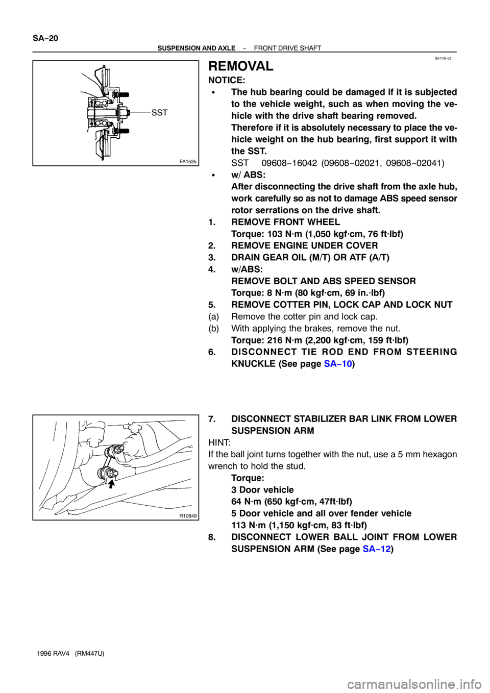
REMOVAL
NOTICE:
�The hub bearing could be damaged if it is subjected
to the vehicle weight, such as when moving the ve-
hicle with the drive shaft bearing removed.
Therefore if it is absolutely necessary to place the ve-
hicle weight on the hub bearing, first support it with
the SST.
SST 09608−16042 (09608−02021, 09608−02041)
�w/ ABS:
After disconnecting the drive shaft from the axle hub,
work carefully so as not to damage ABS speed sensor
rotor serrations on the drive shaft.
1. REMOVE FRONT WHEEL
Torque: 103 N·m (1,050 kgf·cm, 76 ft·lbf)
2. REMOVE ENGINE UNDER COVER
3. DRAIN GEAR OIL (M/T) OR ATF (A/T)
4. w/ABS:
REMOVE BOLT AND ABS SPEED SENSOR
Torque: 8 N·m (80 kgf·cm, 69 in.·lbf)
5. REMOVE COTTER PIN, LOCK CAP AND LOCK NUT
(a) Remove the cotter pin and lock cap.
(b) With applying the brakes, remove the nut.
Torque: 216 N·m (2,200 kgf·cm, 159 ft·lbf)
6. D I S C O N N E C T T I E R O D E N D F R O M S T E E R I N G
KNUCKLE (See page SA−10)
7. DISCONNECT STABILIZER BAR LINK FROM LOWER
SUSPENSION ARM
HINT:
If the ball joint turns together with the nut, use a 5 mm hexagon
wrench to hold the stud.
Torque:
3 Door vehicle
64 N·m (650 kgf·cm, 47ft·lbf)
5 Door vehicle and all over fender vehicle
113 N·m (1,150 kgf·cm, 83 ft·lbf)
8. DISCONNECT LOWER BALL JOINT FROM LOWER
SUSPENSION ARM (See page SA−12)
Page 1135 of 1354

R10840
W01206
2WD M/T RH
W01207
2WD A/T RH
W01208
2WD LH and 4WD RH
W01209
− SUSPENSION AND AXLEFRONT DRIVE SHAFT
SA−21
1996 RAV4 (RM447U)
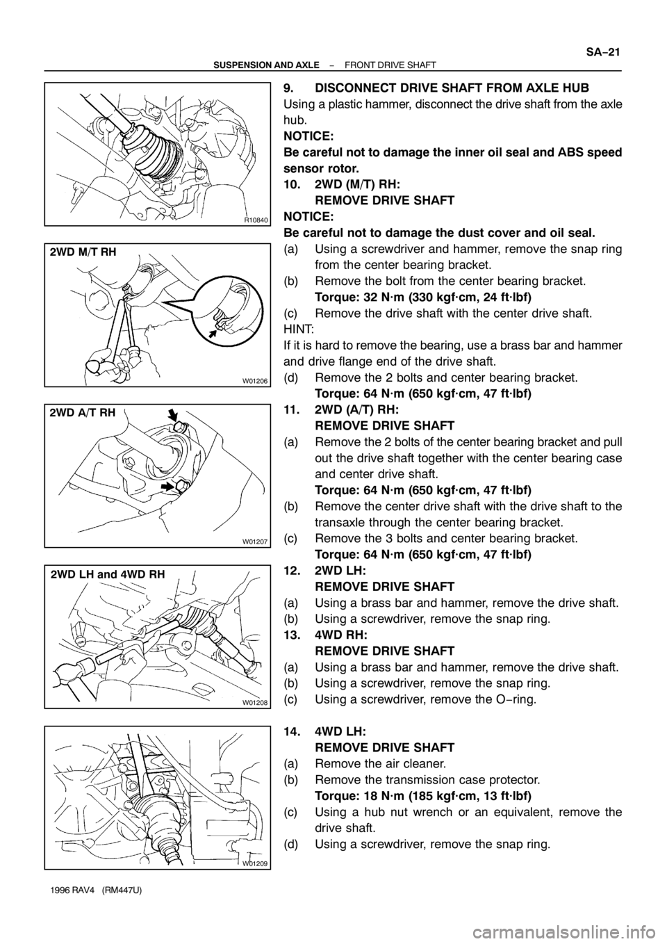
9. DISCONNECT DRIVE SHAFT FROM AXLE HUB
Using a plastic hammer, disconnect the drive shaft from the axle
hub.
NOTICE:
Be careful not to damage the inner oil seal and ABS speed
sensor rotor.
10. 2WD (M/T) RH:
REMOVE DRIVE SHAFT
NOTICE:
Be careful not to damage the dust cover and oil seal.
(a) Using a screwdriver and hammer, remove the snap ring
from the center bearing bracket.
(b) Remove the bolt from the center bearing bracket.
Torque: 32 N·m (330 kgf·cm, 24 ft·lbf)
(c) Remove the drive shaft with the center drive shaft.
HINT:
If it is hard to remove the bearing, use a brass bar and hammer
and drive flange end of the drive shaft.
(d) Remove the 2 bolts and center bearing bracket.
Torque: 64 N·m (650 kgf·cm, 47 ft·lbf)
11. 2WD (A/T) RH:
REMOVE DRIVE SHAFT
(a) Remove the 2 bolts of the center bearing bracket and pull
out the drive shaft together with the center bearing case
and center drive shaft.
Torque: 64 N·m (650 kgf·cm, 47 ft·lbf)
(b) Remove the center drive shaft with the drive shaft to the
transaxle through the center bearing bracket.
(c) Remove the 3 bolts and center bearing bracket.
Torque: 64 N·m (650 kgf·cm, 47 ft·lbf)
12. 2WD LH:
REMOVE DRIVE SHAFT
(a) Using a brass bar and hammer, remove the drive shaft.
(b) Using a screwdriver, remove the snap ring.
13. 4WD RH:
REMOVE DRIVE SHAFT
(a) Using a brass bar and hammer, remove the drive shaft.
(b) Using a screwdriver, remove the snap ring.
(c) Using a screwdriver, remove the O−ring.
14. 4WD LH:
REMOVE DRIVE SHAFT
(a) Remove the air cleaner.
(b) Remove the transmission case protector.
Torque: 18 N·m (185 kgf·cm, 13 ft·lbf)
(c) Using a hub nut wrench or an equivalent, remove the
drive shaft.
(d) Using a screwdriver, remove the snap ring.