Page 921 of 1399

LU0KI−02
LU−12
−
LUBRICATION OIL PUMP
1996 LAND CRUISER (RM451U)
INSTALLATION
1. SET CRANKSHAFT
Turn the crankshaft until the set key on the crankshaft facing
downward.
2. INSTALL TIMING CHAIN AND CAMSHAFT TIMING GEAR (See page EM−19 )
3. INSTALL OIL PUMP (TIMING CHAIN COVER)(See
page EM−19 )
4. INSTALL DRIVE BELT IDLER PULLEY
Install the pulley with the bolt. Torque: 43 N·m (440 kgf·cm, 32 ft·lbf)
5. INSTALL CRANKSHAFT PULLEY (See page EM−19 )
6. INSTALL OIL STRAINER
Install a new gasket and the oil strainer with the bolt and 2 nuts. Torque: 20 N·m (200 kgf·cm, 14 ft·lbf)
7. INSTALL OIL PAN BAFFLE PLATE
Install the baffle plate with the bolt and 7 nuts.
Torque: 9.0 N·m (90 kgf·cm, 78 in.·lbf)
8. INSTALL NO.1 OIL PAN
(a) Remove any old packing (FIPG) material and be careful not to drop any oil on the contact surfaces of the oil pan,
oil pump and cylinder block.
�Using a razor blade and gasket scraper, remove all
the old packing (FIPG) material from the gasket sur-
faces and sealing grooves.
�Thoroughly clean all components to remove all the
loose material.
�Using a non −residue solvent, clean both sealing
surfaces.
(b) Apply seal packing to the No.1 oil pan as shown in the il- lustration.
Seal packing: Part No. 08826−00080 or equivalent
�Install a nozzle that has been cut to a 3 − 4 mm (0.12
− 0.16 in.) opening.
HINT:
Avoid applying an excessive amount to the surface.
�Parts must be assembled within 5 minutes of ap-
plication. Otherwise the material must be removed
and reapplied.
�Immediately remove nozzle from the tube and rein-
stall cap.
Brought to you by BirfMark
Brought to you by BirfMark
Version 1.11 - 03/16/2010
Page 930 of 1399
LU0KM−04
−
LUBRICATION OIL NOZZLE
LU−21
1996 LAND CRUISER (RM451U)
REMOVAL
1. REMOVE CYLINDER HEAD (See page EM−28 )
2. REMOVE TIMING CHAIN AND GEARS (See page EM−13 )
3. REMOVE CRANKSHAFT (See page EM−83 )
4. REMOVE OIL NOZZLES
Remove the 6 check valves and oil nozzles. Torque: 25 N·m (250 kgf·cm, 18 ft·lbf)
HINT:
At the time of installation, align the pin of the nozzle with the pin
hole of the cylinder block.
Brought to you by BirfMark
Brought to you by BirfMark
Version 1.11 - 03/16/2010
Page 944 of 1399
−
PREPARATION ENGINE MECHANICAL
PP−3
52
Author�: Date�:
1996 LAND CRUISER (RM451U)
(09316−00011)Replacer PipeCrankshaft front oil seal
(09316−00051)Replacer ”D”Crankshaft front oil seal
09330−00021Companion Flange Holding ToolCrankshaft pulley
09636−20010Upper Ball Joint Dust Cover
ReplacerCrankshaft timing gear
09816−30010Oil Pressure Switch SocketKnock sensor
09843−18020Diagnosis Check Wire
09950−40011Puller B SetCrankshaft timing gear
(09951−04010)Hanger 150
(09952−04010)Slide Arm
(09953−04020)Center Bolt 150
(09954−04010)Arm 25
(09955−04061)Claw No.6
09950−50012Puller C SetCrankshaft pulley
Brought to you by BirfMark
Brought to you by BirfMark
Version 1.11 - 03/16/2010
Page 945 of 1399
PP−4
−
PREPARATION ENGINE MECHANICAL
53
Author�: Date�:
1996 LAND CRUISER (RM451U)
(09951−05010)Hanger 150
(09952−05010)Slide Arm
(09953−05010)Center Bolt 100
(09953−05020)Center Bolt 150
(09954−05020)Claw No.2
09950−60010Replacer Set
(09951−00280)Replacer 28Connecting rod bushing
(09951−00350)Replacer 35Crankshaft timing gear
(09951−00480)Replacer 48Spark plug tube gasket
09950−70010Handle Set
(09951−07100)Handle 100
(09951−07150)Handle 150
Brought to you by BirfMark
Brought to you by BirfMark
Version 1.11 - 03/16/2010
Page 948 of 1399
PP303−01
−
PREPARATION ENGINE MECHANICAL
PP−7
1996 LAND CRUISER (RM451U)
SSM (Special Service Materials)
08826−00080Seal Packing Black or equivalent
(FIPG)Over space between cylinder block
and timing chain case
Timing cgain cover
Semi−circular plug
Oil pan
Rear oil seal retainer
08833−00070Adhesive 1324,
THREE BOND 1324 or equivalentPlug tube
08833−00080Adhesive 1344
THREE BOND 1344
LOCTITE 242 or equivalentTVV
Brought to you by BirfMark
Brought to you by BirfMark
Version 1.11 - 03/16/2010
Page 961 of 1399
PP30H−01
PP−20
−
PREPARATION LUBRICATION
1996 LAND CRUISER (RM451U)
SSM (Special Service Materials)
08826−00080Seal Packing Black or equivalent
(FIPG)Oil pump
Oil pan (Timing chain cover)
08833−00080Adhesive 1344
THREE BOND 1344
LOCTITE 242 or equivalentOil pressure switch
Brought to you by BirfMark
Brought to you by BirfMark
Version 1.11 - 03/16/2010
Page 1305 of 1399

SS1EO−04
SS−4
−
SERVICE SPECIFICATIONS ENGINE MECHANICAL
127
Author�: Date�:
1996 LAND CRUISER (RM451U)
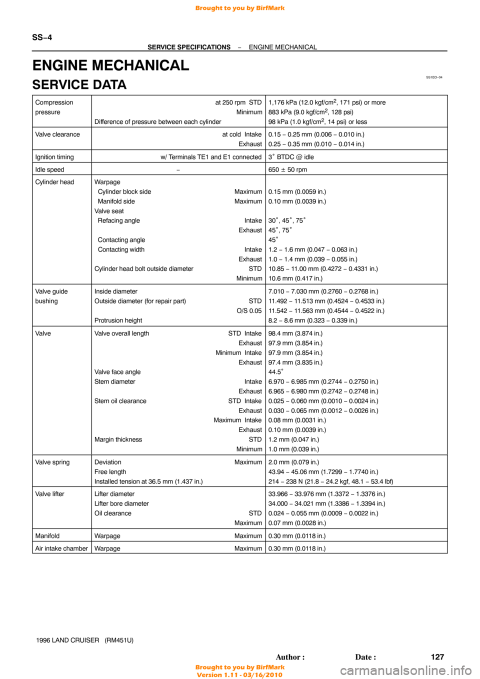
ENGINE MECHANICAL
SERVICE DATA
Compression
pressureat 250 rpm STD
Minimum
Difference of pressure between each cylinder1,176 kPa (12.0 kgf/cm2, 171 psi) or more
883 kPa (9.0 kgf/cm2, 128 psi)
98 kPa (1.0 kgf/cm2, 14 psi) or less
Valve clearanceat cold Intake Exhaust0.15 − 0.25 mm (0.006 − 0.010 in.)
0.25 − 0.35 mm (0.010 − 0.014 in.)
Ignition timingw/ Terminals TE1 and E1 connected3° BTDC @ idle
Idle speed−650 ± 50 rpm
Cylinder headWarpage
Cylinder block side Maximum
Manifold side Maximum
Valve seat
Refacing angle Intake
Exhaust
Contacting angle
Contacting width Intake
Exhaust
Cylinder head bolt outside diameter STD
Minimum
0.15 mm (0.0059 in.)
0.10 mm (0.0039 in.)
30°, 45° , 75°
45 °, 75°
45 °
1.2 − 1.6 mm (0.047 − 0.063 in.)
1.0 − 1.4 mm (0.039 − 0.055 in.)
10.85 − 11.00 mm (0.4272 − 0.4331 in.)
10.6 mm (0.417 in.)
Valve guide
bushingInside diameter
Outside diameter (for repair part) STD O/S 0.05
Protrusion height7.010 − 7.030 mm (0.2760 − 0.2768 in.)
11.492 − 11.513 mm (0.4524 − 0.4533 in.)
11.542 − 11.563 mm (0.4544 − 0.4522 in.)
8.2 − 8.6 mm (0.323 − 0.339 in.)
ValveValve overall length STD Intake
Exhaust
Minimum Intake Exhaust
Valve face angle
Stem diameter Intake
Exhaust
Stem oil clearance STD Intake
Exhaust
Maximum Intake
Exhaust
Margin thickness STD
Minimum98.4 mm (3.874 in.)
97.9 mm (3.854 in.)
97.9 mm (3.854 in.)
97.4 mm (3.835 in.)
44.5 °
6.970 − 6.985 mm (0.2744 − 0.2750 in.)
6.965 − 6.980 mm (0.2742 − 0.2748 in.)
0.025 − 0.060 mm (0.0010 − 0.0024 in.)
0.030 − 0.065 mm (0.0012 − 0.0026 in.)
0.08 mm (0.0031 in.)
0.10 mm (0.0039 in.)
1.2 mm (0.047 in.)
1.0 mm (0.039 in.)
Valve springDeviation Maximum
Free length
Installed tension at 36.5 mm (1.437 in.)2.0 mm (0.079 in.)
43.94 − 45.06 mm (1.7299 − 1.7740 in.)
214 − 238 N (21.8 − 24.2 kgf, 48.1 − 53.4 lbf)
Valve lifterLifter diameter
Lifter bore diameter
Oil clearance STD
Maximum33.966 − 33.976 mm (1.3372 − 1.3376 in.)
34.000 − 34.021 mm (1.3386 − 1.3394 in.)
0.024 − 0.055 mm (0.0009 − 0.0022 in.)
0.07 mm (0.0028 in.)
ManifoldWarpage Maximum0.30 mm (0.0118 in.)
Air intake chamberWarpageMaximum0.30 mm (0.0118 in.)
Brought to you by BirfMark
Brought to you by BirfMark
Version 1.11 - 03/16/2010
Page 1306 of 1399

−
SERVICE SPECIFICATIONS ENGINE MECHANICAL
SS−5
128
Author�: Date�:
1996 LAND CRUISER (RM451U)
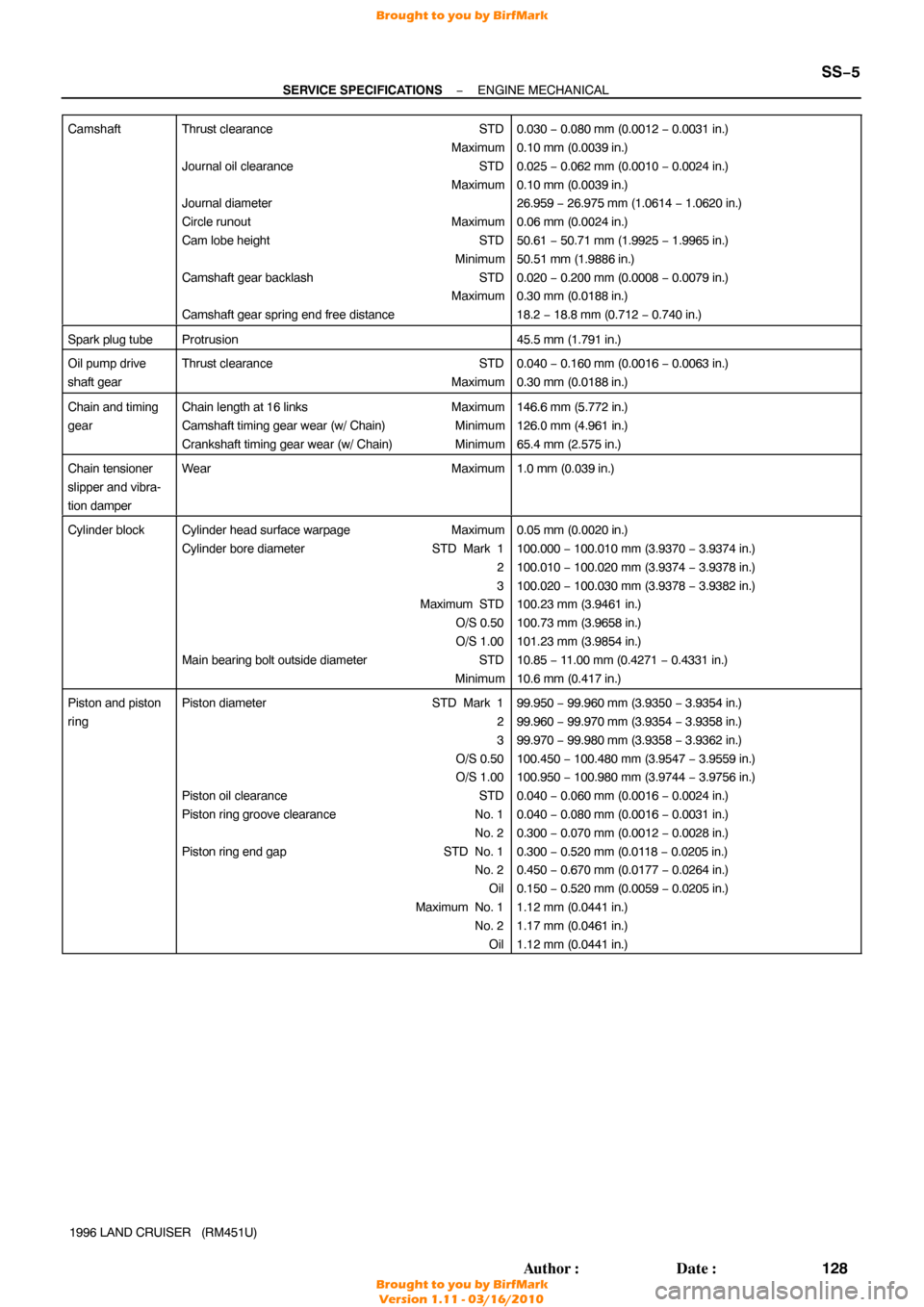
Camshaft
Thrust clearance
STD
Maximum
Journal oil clearance STD
Maximum
Journal diameter
Circle runout Maximum
Cam lobe height STD
Minimum
Camshaft gear backlash STD
Maximum
Camshaft gear spring end free distance0.030 − 0.080 mm (0.0012 − 0.0031 in.)
0.10 mm (0.0039 in.)
0.025 − 0.062 mm (0.0010 − 0.0024 in.)
0.10 mm (0.0039 in.)
26.959 − 26.975 mm (1.0614 − 1.0620 in.)
0.06 mm (0.0024 in.)
50.61 − 50.71 mm (1.9925 − 1.9965 in.)
50.51 mm (1.9886 in.)
0.020 − 0.200 mm (0.0008 − 0.0079 in.)
0.30 mm (0.0188 in.)
18.2 − 18.8 mm (0.712 − 0.740 in.)
Spark plug tubeProtrusion45.5 mm (1.791 in.)
Oil pump drive
shaft gearThrust clearance STD
Maximum0.040 − 0.160 mm (0.0016 − 0.0063 in.)
0.30 mm (0.0188 in.)
Chain and timing
gearChain length at 16 links Maximum
Camshaft timing gear wear (w/ Chain) Minimum
Crankshaft timing gear wear (w/ Chain) Minimum146.6 mm (5.772 in.)
126.0 mm (4.961 in.)
65.4 mm (2.575 in.)
Chain tensioner
slipper and vibra-
tion damperWearMaximum1.0 mm (0.039 in.)
Cylinder blockCylinder head surface warpageMaximum
Cylinder bore diameter STD Mark 1
2
3
Maximum STD
O/S 0.50
O/S 1.00
Main bearing bolt outside diameter STD
Minimum0.05 mm (0.0020 in.)
100.000 − 100.010 mm (3.9370 − 3.9374 in.)
100.010 − 100.020 mm (3.9374 − 3.9378 in.)
100.020 − 100.030 mm (3.9378 − 3.9382 in.)
100.23 mm (3.9461 in.)
100.73 mm (3.9658 in.)
101.23 mm (3.9854 in.)
10.85 − 11.00 mm (0.4271 − 0.4331 in.)
10.6 mm (0.417 in.)
Piston and piston
ringPiston diameter STD Mark 1
2
3
O/S 0.50
O/S 1.00
Piston oil clearance STD
Piston ring groove clearance No. 1
No. 2
Piston ring end gap STD No. 1
No. 2
Oil
Maximum No. 1 No. 2Oil99.950 − 99.960 mm (3.9350 − 3.9354 in.)
99.960 − 99.970 mm (3.9354 − 3.9358 in.)
99.970 − 99.980 mm (3.9358 − 3.9362 in.)
100.450 − 100.480 mm (3.9547 − 3.9559 in.)
100.950 − 100.980 mm (3.9744 − 3.9756 in.)
0.040 − 0.060 mm (0.0016 − 0.0024 in.)
0.040 − 0.080 mm (0.0016 − 0.0031 in.)
0.300 − 0.070 mm (0.0012 − 0.0028 in.)
0.300 − 0.520 mm (0.0118 − 0.0205 in.)
0.450 − 0.670 mm (0.0177 − 0.0264 in.)
0.150 − 0.520 mm (0.0059 − 0.0205 in.)
1.12 mm (0.0441 in.)
1.17 mm (0.0461 in.)
1.12 mm (0.0441 in.)
Brought to you by BirfMark
Brought to you by BirfMark
Version 1.11 - 03/16/2010