Page 818 of 1399

P22143A16076
2 Dot Marks
−
ENGINE MECHANICAL CYLINDER HEAD
EM−33
1996 LAND CRUISER (RM451U)
(d) Remove the camshaft timing gear and chain from the in-
take camshaft and leave on the slipper and damper.
35. REMOVE CAMSHAFTS
NOTICE:
Since the thrust clearance of the camshaft is small, the
camshaft must be kept level while it is being removed. If the
camshaft is not kept level, the portion of the cylinder head
receiving the shaft thrust may crack or be damaged, caus-
ing the camshaft to seize or break. To avoid this, the follow-
ing steps should be carried out.
(a) Remove the exhaust camshaft. (1) Bring the service bolt hole of the driven sub −gear
upward by turning the hexagon wrench head por-
tion of the exhaust camshaft with a wrench.
(2) Secure the exhaust camshaft sub −gear to the main
gear with a service bolt.
Recommended service bolt:
Thread diameter6 mm
Thread pitch1.0 mm
Bolt length16 − 20 mm (0.63 − 0.79 in.)
HINT:
When removing the camshaft, make sure that the torsional
spring force of the sub −gear has been eliminated by the above
operation.
(3) Set the timing mark (2 dot marks) of the camshaftdriven gear at approx. 35 ° angle by turning the
hexagon wrench head portion of the intake cam-
shaft with a wrench.
(4) Lightly push the camshaft towards the rear without applying excessive force.
(5) Loosen and remove the No. 1 bearing cap bolts, al-
ternately loosening the left and right bolts uniformly.
Brought to you by BirfMark
Brought to you by BirfMark
Version 1.11 - 03/16/2010
Page 819 of 1399

P22567A16077
2 Dot Marks
EM−34
−
ENGINE MECHANICAL CYLINDER HEAD
1996 LAND CRUISER (RM451U)
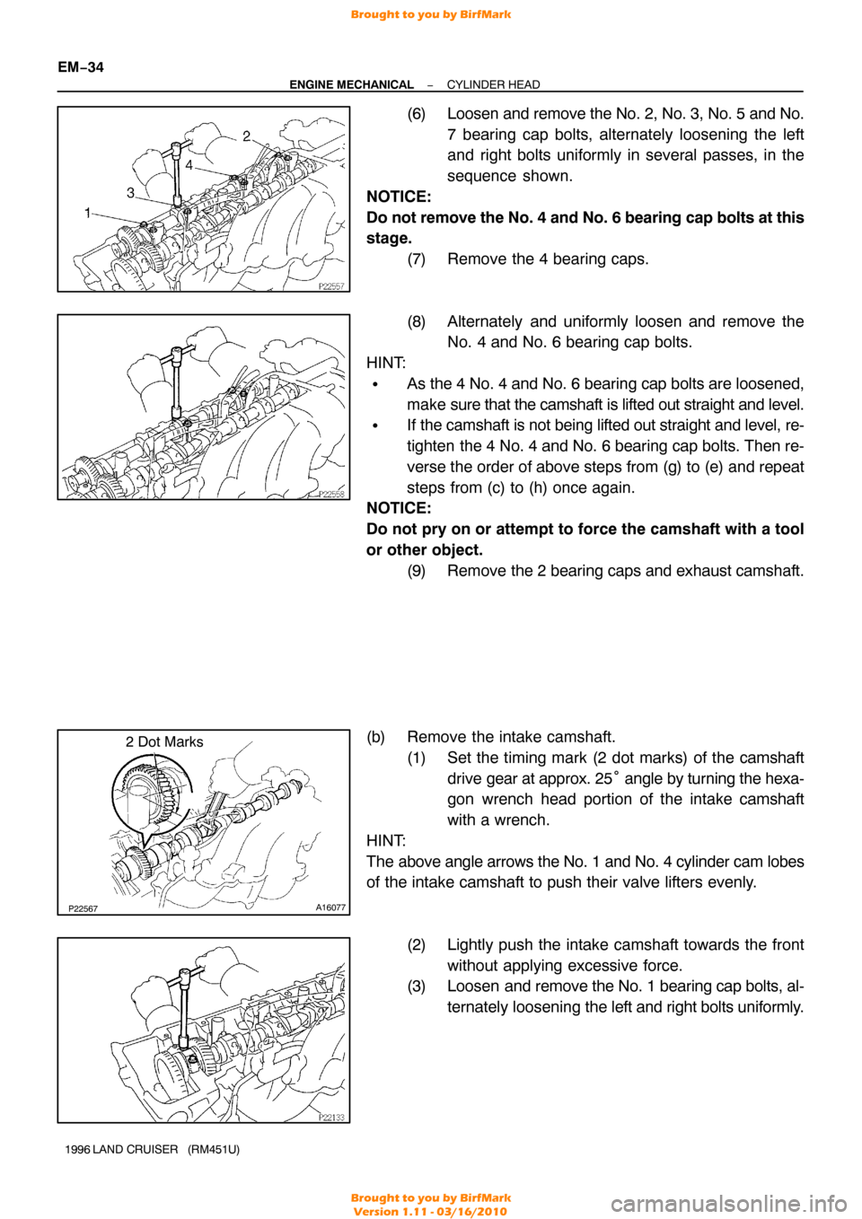
(6) Loosen and remove the No. 2, No. 3, No. 5 and No.
7 bearing cap bolts, alternately loosening the left
and right bolts uniformly in several passes, in the
sequence shown.
NOTICE:
Do not remove the No. 4 and No. 6 bearing cap bolts at this
stage. (7) Remove the 4 bearing caps.
(8) Alternately and uniformly loosen and remove theNo. 4 and No. 6 bearing cap bolts.
HINT:
�As the 4 No. 4 and No. 6 bearing cap bolts are loosened,
make sure that the camshaft is lifted out straight and level.
�If the camshaft is not being lifted out straight and level, re-
tighten the 4 No. 4 and No. 6 bearing cap bolts. Then re-
verse the order of above steps from (g) to (e) and repeat
steps from (c) to (h) once again.
NOTICE:
Do not pry on or attempt to force the camshaft with a tool
or other object.
(9) Remove the 2 bearing caps and exhaust camshaft.
(b) Remove the intake camshaft. (1) Set the timing mark (2 dot marks) of the camshaftdrive gear at approx. 25 ° angle by turning the hexa-
gon wrench head portion of the intake camshaft
with a wrench.
HINT:
The above angle arrows the No. 1 and No. 4 cylinder cam lobes
of the intake camshaft to push their valve lifters evenly.
(2) Lightly push the intake camshaft towards the frontwithout applying excessive force.
(3) Loosen and remove the No. 1 bearing cap bolts, al-
ternately loosening the left and right bolts uniformly.
Brought to you by BirfMark
Brought to you by BirfMark
Version 1.11 - 03/16/2010
Page 841 of 1399

P22567A16077
2 Dot Marks
EM−56
−
ENGINE MECHANICAL CYLINDER HEAD
1996 LAND CRUISER (RM451U)
(a) Install the intake camshaft.
(1) Apply engine oil to the thrust portion of the intakecamshaft.
(2) Lightly place the intake camshaft on top of the cylin-
der head as shown in the illustration so that the No.
1 and No. 4 cylinder cam lobes face downward.
(3) Lightly push the camshaft towards the front without
applying excessive force.
(4) Place the No. 2 and No. 5 bearing caps in their prop-
er location.
(5) Temporarily tighten these bearing cap bolts uni- formly and alternately in several passes until the
bearing caps are snug with the cylinder head.
(6) Place the No. 3, No. 4, No. 6 and No. 7 bearing caps
in their proper location.
(7) Temporarily tighten these bearing cap bolts, alter- nately tightening the left and right bolts uniformly.
(8) Place the No. 1 bearing cap in its proper location. When doing this, check that there is no gap be-
tween the cylinder head and the contact surface of
bearing cap.
(9) Temporarily tighten the bearing cap bolts, alternate-
ly tightening the left and right bolts uniformly.
(10) Uniformly tighten the 14 bearing cap bolts in several
passes.
Torque: 16 N·m (160 kgf·cm, 12 ft·lbf)
(b) Install the exhaust camshaft. (1) Set the timing mark (2 dot marks) of the camshaftdrive gear at approx. 35 ° angle by turning the hexa-
gon wrench head portion of the intake camshaft
with a wrench.
Brought to you by BirfMark
Brought to you by BirfMark
Version 1.11 - 03/16/2010
Page 842 of 1399

−
ENGINE MECHANICAL CYLINDER HEAD
EM−57
1996 LAND CRUISER (RM451U)
(2) Apply engine oil to thrust portion of the exhaust
camshaft.
(3) Engage the exhaust camshaft gear to the intake
camshaft gear by matching the timing marks (two
dot marks) on each gear.
(4) Roll down the exhaust camshaft onto the bearing journals while engaging gears with each other.
(5) Lightly push the intake camshaft towards the front without applying excessive force.
(6) Install the No. 4 and No. 6 bearing caps in their proper location.
(7) Temporarily tighten the bearing cap bolts uniformly and alternately in several passes until the bearing
caps are snug with the cylinder head.
(8) Place the No. 2, No. 3, No. 5 and No. 7 bearing caps
in their proper location.
(9) Temporarily tighten these bearing cap bolts, alter- nately tightening the left and right bolts uniformly.
(10) Place the No. 1 bearing cap in its proper location. When doing this, check that there is no gap be-
tween the cylinder head and the contact surface of
bearing cap.
(11) Temporarily tighten the bearing cap bolts, alternate-
ly tightening the left and right bolts uniformly.
(12) Uniformly tighten the 14 bearing cap bolts in several
passes.
Torque: 16 N·m (160 kgf·cm, 12 ft·lbf)
(13) Bring the service bolt installed in the driven sub −
gear upward by turning the hexagon wrench head
portion of the camshaft with a wrench.
(14) Remove the service bolt.
(15) Check that the intake and exhaust camshafts turn smoothly.
Brought to you by BirfMark
Brought to you by BirfMark
Version 1.11 - 03/16/2010
Page 843 of 1399
P08374A16075
1 Dot Mark
EM−58
−
ENGINE MECHANICAL CYLINDER HEAD
1996 LAND CRUISER (RM451U)
4. SET NO.1 CYLINDER TO TDC/COMPRESSION
(a) Turn the crankshaft pulley, and align its groove with the
timing mark ”0” of the timing chain cover.
(b) Turn the camshafts so that the timing marks with 1 and 2 dots will be in straight line on the cylinder head surface as
shown in the illustration.
5. INSTALL CAMSHAFT TIMING GEAR
HINT:
Check that the matchmarks on the camshaft timing gear and
timing chain are aligned.
(a) Place the gear over the straight pin of the intake cam- shaft.
(b) Align the straight pin of distributor gear with the straight pin groove of the intake camshaft gear as shown.
(c) Hold the intake camshaft with a wrench, install and torque
the bolt.
Torque: 74 N·m (750 kgf·cm, 54 ft·lbf)
Brought to you by BirfMark
Brought to you by BirfMark
Version 1.11 - 03/16/2010
Page 844 of 1399

Front Mark
P09890
Push
P08374A16075
1 Dot Mark
−
ENGINE MECHANICAL CYLINDER HEAD
EM−59
1996 LAND CRUISER (RM451U)
6. INSTALL CHAIN TENSIONER
(a) Place a new gasket so that the front mark is toward the
front side.
(b) Push the tensioner by hand until it touches the head installation surface, then install the 2 nuts.
(c) Tighten the 2 nuts. Torque: 21 N·m (210 kgf·cm, 15 ft·lbf)
7. CHECK VALVE TIMING
(a) Turn the crankshaft pulley, and align its groove with the timing mark ”0” of the timing chain cover.
NOTICE:
Always turn the crankshaft clockwise.
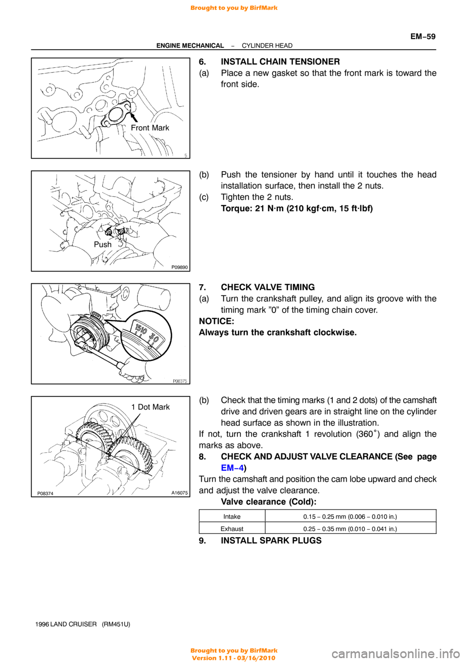
(b) Check that the timing marks (1 and 2 dots) of the camshaft
drive and driven gears are in straight line on the cylinder
head surface as shown in the illustration.
If not, turn the crankshaft 1 revolution (360° ) and align the
marks as above.
8. CHECK AND ADJUST VALVE CLEARANCE (See page
EM−4)
Turn the camshaft and position the cam lobe upward and check
and adjust the valve clearance.
Valve clearance (Cold):
Intake0.15 − 0.25 mm (0.006 − 0.010 in.)
Exhaust0.25 − 0.35 mm (0.010 − 0.041 in.)
9. INSTALL SPARK PLUGS
Brought to you by BirfMark
Brought to you by BirfMark
Version 1.11 - 03/16/2010
Page 845 of 1399

P03789
P08374A16075
1 Dot Mark
EM−60
−
ENGINE MECHANICAL CYLINDER HEAD
1996 LAND CRUISER (RM451U)
10. INSTALL SEMI −CIRCULAR PLUG
(a) Remove any old packing (FIPG) material.
(b) Apply seal packing to the cylinder head installation sur- face of the semi−circular plug.
Seal packing: Part No. 08826−00080 or equivalent
(c) Install the semi −circular plug to the cylinder head.
11. SET NO. 1 CYLINDER TO TDC/COMPRESSION
(a) Turn the crankshaft pulley, and align its groove with the timing mark ”0” of the timing chain cover.
(b) Check that the timing marks with 1 and 2 dots are in straight line on the cylinder head surface as shown in the
illustration.
If not, turn the crankshaft 1 revolution (360°) and align the mark
as above.
12. INSTALL CYLINDER HEAD COVER
(a) Install the gasket to the cylinder head cover.
(b) Install the cylinder head cover with the 13 bolts.
13. INSTALL WATER BYPASS OUTLET AND PIPE
(a) Install a new O−ring to the water bypass outlet.
(b) Install 2 new O−rings to the water bypass pipe.
(c) Apply soapy water to the O−rings.
(d) Assemble the water bypass outlet and pipe.
(e) Install the water bypass outlet and pipe with the 2 bolts.
Torque: 21 N·m (210 kgf·cm, 15 ft·lbf)
Brought to you by BirfMark
Brought to you by BirfMark
Version 1.11 - 03/16/2010
Page 849 of 1399
EM−64
−
ENGINE MECHANICAL CYLINDER HEAD
1996 LAND CRUISER (RM451U)
39. INSTALL AIR CLEANER HOSE AND CAP
40. INSTALL BATTERY TRAY AND BATTERY
(a) Install the battery tray with the 5 bolts.
(b) Connect the ground strap with the bolt.
(c) Install the battery and hold−down clamp with the nuts.
(d) Connect the battery cables.
41. FILL RADIATOR WITH ENGINE COOLANT
42. START ENGINE AND CHECK FOR LEAKS
43. ADJUST IGNITION TIMING (See page EM−10)
44. PERFORM ROAD TEST
Check for abnormal noise, shock, slippage, correct shift points
and smooth operation.
45. RECHECK ENGINE COOLANT LEVEL
Brought to you by BirfMark
Brought to you by BirfMark
Version 1.11 - 03/16/2010