Page 858 of 1399

−
ENGINE MECHANICAL ENGINE UNIT
EM−73
1996 LAND CRUISER (RM451U)
(g) Disconnect the 3 connectors.
(h) Remove the 10 bolts and the transfer shift lever boot and
transmission shift lever assembly.
(i) Pull out the pin and disconnect the shift rod.
(j) Remove the 4 bolts, hose clamp and the transfer shift le- ver.
26. REMOVE FRONT EXHAUST PIPE
(a) Disconnect the heated oxygen sensor connector.
(b) Remove the 2 nuts and 2 bolts holding the front exhaust pipe to the rear TWC.
(c) Disconnect the front exhaust pipe, and remove the gas- ket.
(d) Loosen the clamp bolt and disconnect the clamp from the
No.1 support bracket.
(e) Remove the 2 bolts and No. 1 support bracket.
(f) Remove the 4 nuts, front exhaust pipe and 2 gaskets.
27. DISCONNECT GROUND STRAP FROM HEAT INSULA-
TOR
28. PLACE JACK UNDER TRANSMISSION
Be sure to put a wooden block between the jack and the trans-
mission oil pan to prevent damage.
Brought to you by BirfMark
Brought to you by BirfMark
Version 1.11 - 03/16/2010
Page 859 of 1399

EM−74
−
ENGINE MECHANICAL ENGINE UNIT
1996 LAND CRUISER (RM451U)
29. REMOVE FRAME CROSSMEMBER
(a) Remove the 2 nuts holding the crossmember to the en-
gine rear mounting insulator.
(b) Remove the 8 bolts and crossmember.
30. REMOVE ENGINE WITH TRANSMISSION
(a) Attach the engine hoist chain to the 2 engine hangers.
(b) Remove the 2 nuts holding the engine front mounting in- sulators to the frame.
(c) Lift the engine with transmission out of the vehicle slowly
and carefully.
NOTICE:
Make sure that the engine is clear of all wiring and hoses.
(d) Place the engine and transmission assembly onto the stand.
31. REMOVE OIL DIPSTICK GUIDE FOR TRANSMISSION
(a) Disconnect the 2 breather hoses.
(b) Remove the 2 mounting bolts.
(c) Pull out the dipstick guide and dipstick from the transmis- sion.
(d) Remove the O−ring from the dipstick guide.
32. DISCONNECT ENGINE WIRE FROM TRANSMISSION
(a) Disconnect the PNP switch connector.
(b) Disconnect the 2 connectors from the transmission.
Brought to you by BirfMark
Brought to you by BirfMark
Version 1.11 - 03/16/2010
Page 925 of 1399
LU0KK−02
LU−16
−
LUBRICATION OIL COOLER
1996 LAND CRUISER (RM451U)
REMOVAL
1. DRAIN ENGINE COOLANT
2. REMOVE AIR CLEANER CAP AND HOSE
3. REMOVE FRONT EXHAUST PIPE
(a) Disconnect the heated oxygen sensor connector.
(b) Remove the 2 nuts and 2 bolts holding the front exhaust pipe to the rear TWC.
(c) Disconnect the front exhaust pipe, and remove the gas- ket.
(d) Loosen the clamp bolt and disconnect the clamp from the
No.1 support bracket.
(e) Remove the 2 bolts and No.1 support bracket.
(f) Remove the 4 nuts, front exhaust pipe and 2 gaskets.
4. REMOVE NO.1 EXHAUST MANIFOLD
(a) Remove the 3 bolts and No.1 heat insulator.
(b) Remove the 6 nuts, exhaust manifold and gasket.
Brought to you by BirfMark
Brought to you by BirfMark
Version 1.11 - 03/16/2010
Page 938 of 1399

MA0055
MA02T−03
MA−6
−
MAINTENANCE BRAKE
46
Author�: Date�:
1996 LAND CRUISER (RM451U)
BRAKE
INSPECTION
1. INSPECT BRAKE LINE PIPES AND HOSES
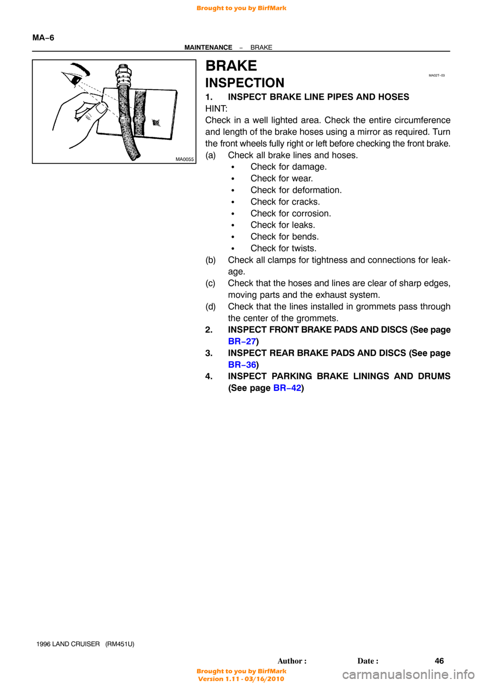
HINT:
Check in a well lighted area. Check the entire circumference
and length of the brake hoses using a mirror as required. Turn
the front wheels fully right or left before checking the front brake.
(a) Check all brake lines and hoses.
�Check for damage.
�Check for wear.
�Check for deformation.
�Check for cracks.
�Check for corrosion.
�Check for leaks.
�Check for bends.
�Check for twists.
(b) Check all clamps for tightness and connections for leak- age.
(c) Check that the hoses and lines are clear of sharp edges, moving parts and the exhaust system.
(d) Check that the lines installed in grommets pass through the center of the grommets.
2. INSPECT FRONT BRAKE P ADS AND DISCS (See page
BR−27 )
3. INSPECT REAR BRAKE PADS AND DISCS (See page
BR−36 )
4. INSPECT PARKING BRAKE LININGS AND DRUMS
(See page BR−42 )
Brought to you by BirfMark
Brought to you by BirfMark
Version 1.11 - 03/16/2010
Page 1025 of 1399

RS0OZ−02
−
SUPPLEMENTAL RESTRAINT SYSTEM SRS AIRBAG
RS−1
1100
Author�: Date�:
1996 LAND CRUISER (RM451U)
SRS AIRBAG
PRECAUTION
NOTICE:
�The LAND CRUISER is equipped with an SRS , which comprises a driver airbag \
and a front pas-
senger airbag. Failure to carry out service operations in the correct sequence could cause the
SRS to unexpectedly deploy during servicing, possibly leading to a serio\
us accident. Further,
if a mistake is made in servicing the SRS, it is possible the SRS may fail to\
operate when re-
quired. Before performing servicing (including removal or installation \
of parts, inspection or
replacement), be sure to read the following items carefully, then follow the correct procedure
described in the repair manual.
�Malfunction symptoms of the SRS are difficult to confirm, so the DTCs become the mos\
t impor-
tant source of information when troubleshooting. When troubleshooting th\
e SRS, always in-
spect the DTCs before disconnecting the battery.
�Even in cases of a minor collision where the SRS does not deploy, the steering wheel pad, front
passenger airbag assembly, and airbag sensor assembly should be inspected (See pages
RS−9 , RS−23 and RS−34 )
�Never use SRS parts from another vehicle. When replacing parts, replace them with \
new parts.
�Never disassemble and repair the steering wheel pad, front passenger airbag assembly , or air-
bag sensor assembly in order to reuse it.
�If the steering wheel pad, front passenger airbag assembly or airbag sen\
sor assembly have
been dropped, or if there are cracks, dents or other defects in the case, br\
acket or connector,
replace them with new ones.
�Use a volt/ohmmeter wi th high impedance (10 k Ω/V minimum) for troubleshooting the system’s
electrical circuits.
�Information labels are attached to the periphery of the SRS components. Follow the instruc-
tions on the notices.
�After work on the SRS is completed, check the SRS warning light (See pa\
ge DI−240).
�If the vehicle is equipped with a mobile communication system, refer to the precaution in the
IN section.
CAUTION:
�Work must be started after 90 seconds from the time the ignition switch is t\
urned to the ”LOCK”
position and the negative ( −) terminal cable is disconnected from the battery.
(The SRS is equipped with a back− up power source so that if work is started within 90 seconds
of disconnecting the negative ( −) terminal cable of the battery, the SRS may be deployed.)
�When the negative (−) terminal cable is disconnected from the battery, the memory of the clock
and audio system will be canceled. So before starting work, make a record o\
f the contents mem-
orized in the audio memory system. When work is finished, reset the audio syst\
ems as they
were before and adjust the clock. To avoid erasing the memory of each memory system, never
use a back−up power supply from outside the vehicle.
�Before repairs, remove the airbag sensor if shocks are likely to be applied to the senso\
r during
repairs.
�Do not expose the steering wheel pad, front passenger airbag assembly, or airbag sensor as-
sembly directly to hot air or flames.
Brought to you by BirfMark
Brought to you by BirfMark
Version 1.11 - 03/16/2010
Page 1030 of 1399

Z05490
Secondary LockPrimary Lock Lock Lock
Primary Lock Incomplate
(Secondary Lock Prevended) Primary Lock Complate
(Secondary Lock Permitted
Twin−Lock Complated
Z14034
Fig.1
Fig.2 Power Source
SafingSensor Squibs
Airbag
Sensor
RS−6
−
SUPPLEMENTAL RESTRAINT SYSTEM SRS AIRBAG
1996 LAND CRUISER (RM451U)
(4) Connector Twin −Lock Mechanism
With this mechanism connectors (male and female
connectors) are locked by 2 locking devices to in-
crease connection reliability. If the primary lock is in-
complete, ribs interfere and prevent the secondary
lock.
(b) When the vehicle is involved in a frontal collision in the hatched area (Fig. 1) and the shock is larger than the pre-
determined level, the SRS is activated automatically. A
safing sensor is designed to go on at a smaller decelera-
tion rate than the airbag sensor. As illustrated in Fig. 2,
ignition is caused when current flows to the squib, which
happens when a safing sensor and the airbag sensor go
on simultaneously.When a deceleration force acts on the
sensors, two squibs in the driver airbag and front passen-
ger airbag ignite and generate gas. The gas discharging
into the driver airbag and front passenger airbag rapidly
increases the pressure inside the bags, breaking open
the steering wheel pad and instrument panel door.
Bag inflation then ends, and the bags deflate as the gas
is discharged through discharge holes at the bag’s rear or
side.
Brought to you by BirfMark
Brought to you by BirfMark
Version 1.11 - 03/16/2010
Page 1046 of 1399

RS0P8−01
RS−22
−
SUPPLEMENTAL RESTRAINT SYSTEM FRONT PASSENGER AIRBAG ASSEMBLY
1996 LAND CRUISER (RM451U)
REMOVAL
NOTICE:
If the wiring connector of the SRS is disconnected with the
ignition switch at ON or ACC, DTCs will be recorded.
1. DISCONNECT AIRBAG CONNECTOR
(a) Remove the glove compartment door (See page BO−76 ).
(b) Remove the airbag connector from the airbag bracket.
NOTICE:
When handling the airbag connector , take care not to dam-
age the airbag wire harness.
(c) Disconnect the airbag connector.
2. REMOVE INSTRUMENT PANEL
(See pages BO−76 )
3. REMOVE FRONT PASSENGER AIRBAG ASSEMBLY
(a) Remove the 4 bolts and 2 nuts, and remove front passen-
ger airbag assembly.
(b) Pry up the 6 clips shown in the illustration and remove the airbag door.
CAUTION:
Do not store the front passenger airbag assembly with the
airbag deployment direction facing down.Never disas-
semble the front passenger airbag assembly.
Brought to you by BirfMark
Brought to you by BirfMark
Version 1.11 - 03/16/2010
Page 1047 of 1399

RS0P9−01
−
SUPPLEMENTAL RESTRAINT SYSTEM FRONT PASSENGER AIRBAG ASSEMBLY
RS−23
1996 LAND CRUISER (RM451U)
INSPECTION
1. VEHICLES NOT INVOLVED IN COLLISION
(a) Do a diagnostic system check (See page DI−240).
(b) Do a visual check which includes the following items with the front passenger airbag assembly installed in the ve-
hicle.
Check cuts, minute cracks or marked discoloration on the
front passenger airbag assembly and instrument panel.
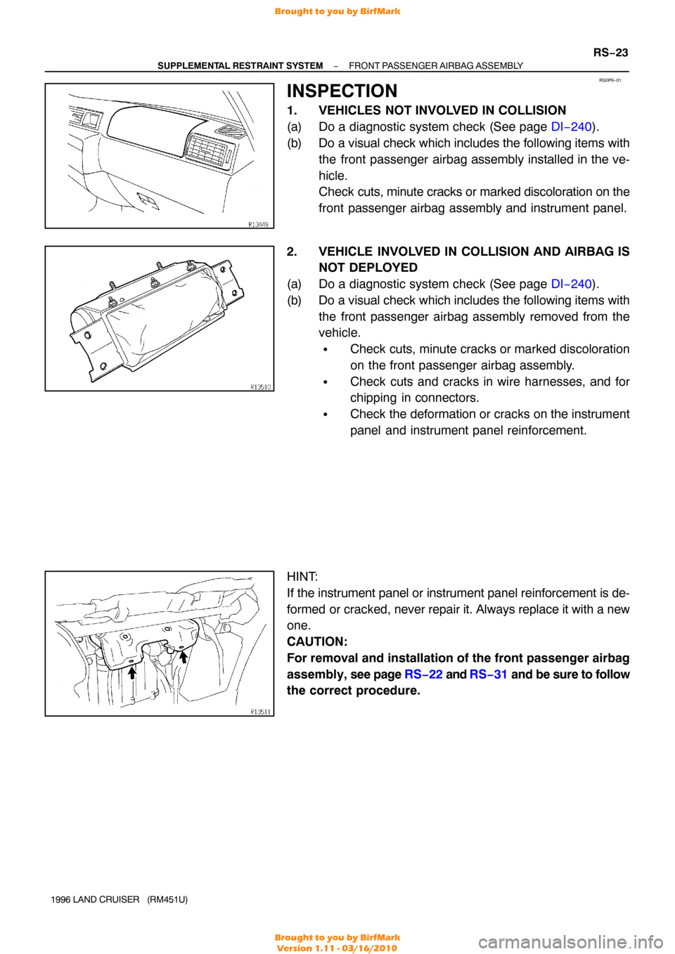
2. VEHICLE INVOLVED IN COLLISION AND AIRBAG IS NOT DEPLOYED
(a) Do a diagnostic system check (See page DI−240).
(b) Do a visual check which includes the following items with the front passenger airbag assembly removed from the
vehicle.
�Check cuts, minute cracks or marked discoloration
on the front passenger airbag assembly.
�Check cuts and cracks in wire harnesses, and for
chipping in connectors.
�Check the deformation or cracks on the instrument
panel and instrument panel reinforcement.
HINT:
If the instrument panel or instrument panel reinforcement is de-
formed or cracked, never repair it. Always replace it with a new
one.
CAUTION:
For removal and installation of the front passenger airbag
assembly, see page RS−22 and RS−31 and be sure to follow
the correct procedure.
Brought to you by BirfMark
Brought to you by BirfMark
Version 1.11 - 03/16/2010