Page 304 of 1399

BO−64
−
BODY SLIDING ROOF
1996 LAND CRUISER (RM451U)
11. REMOVE FRONT SEAT OUTER BELT SHOULDER AN-
CHOR
12. REMOVE CENTER PILLAR UPPER GARNISH
13. REMOVE FRONT SHOULDER BELT ANCHOR AD-
JUSTER
14. REMOVE NO. 1 REAR SEAT OUTER BELT SHOUL- DER ANCHOR
15. w/ No. 2 Rear Seat REMOVE NO. 2 REAR SEAT OUTER BELT SHOUL-
DER ANCHOR
16. REMOVE QUARTER AND REAR PILLAR GARNISH
17. REMOVE ASSIST GRIPS
18. REMOVE FRONT PILLAR GARNISH
19. REMOVE SUN VISORS AND HOLDERS
20. REMOVE INNER REAR VIEW MIRROR
21. REMOVE PERSONAL LIGHT ASSEMBLY AND PER- SONAL LIGHT COVER
22. REMOVE NO. 1 AND NO. 2 ROOM LIGHT
23. REMOVE BACK DOOR OPENING TRIM
24. REMOVE SLIDING ROOF OPENING MOULDING
25. REMOVE CONTROL SWITCH
(a) Remove the screw.
(b) Using a screwdriver, remove the switch cover.
(c) Remove the 2 screws and switch body, then disconnect the connector.
(d) Remove the 2 screws and bracket.
26. REMOVE ROOF HEADLINING
(a) Using the clip remover, remove the 7 clips.
(b) Remove the roof headlining.
Brought to you by BirfMark
Brought to you by BirfMark
Version 1.11 - 03/16/2010
Page 307 of 1399
BO394−01
−
BODY SLIDING ROOF
BO−67
1996 LAND CRUISER (RM451U)
DISASSEMBLY
1. DISCONNECT SLIDING ROOF GUIDE RAIL AND
CABLE GUIDE CASING
(a) Remove the screw and guide rail cover.
(b) Remove the screw.
(c) Pull out the cable guide casing.
2. REMOVE SLIDING GUIDE RAIL
(a) Make the drive cable to the front edge.
(b) Remove the 4 screws and both side drive rails.
(c) Remove the sunshade trim.
Brought to you by BirfMark
Brought to you by BirfMark
Version 1.11 - 03/16/2010
Page 317 of 1399

−
BODY INSTRUMENT PANEL
BO−77
1996 LAND CRUISER (RM451U)
15. REMOVE CENTER CLUSTER FINISH PANEL WITH
HEATER CONTROL ASSEMBLY
(a) Using a screwdriver, take off the 2 claws, then remove the
cup holder hole cover.
HINT:
Tape the screwdriver tip before use.
(b) Take off the ashtray.
(c) Remove the center cluster finish panel with heater control
assembly, then disconnect the connectors.
(d) Remove the 2 screws and heater control assembly from the center cluster finish panel.
16. REMOVE RADIO
17. REMOVE GLOVE COMPARTMENT DOOR
18. REMOVE SPEAKER PANEL AND SPEAKER
19. REMOVE FRONT AND REAR CONSOLE BOX
20. DISCONNECT AIRBAG CONNECTOR
(a) Remove the airbag connector from the airbag bracket.
NOTICE:
When handling the airbag connector , take care not to dam-
age the airbag wire harness.
(b) Disconnect the airbag connector.
21. REMOVE INSTRUMENT PANEL
(a) Remove the 5 screws and 9 bolts.
(b) Remove the instrument panel. Torque: 20 N·m (210 kgf·cm, 15 ft·lbf) for passenger
airbag bolts
22. REMOVE INSTRUMENT PANEL REINFORCEMENT
(a) Remove the 2 bolts and lower instrument panel reinforce-
ment.
(b) Remove the 2 bolts, 2 nuts and No. 1 brace.
(c) Remove the 4 bolts, 4 nuts and instrument panel rein- forcement.
Brought to you by BirfMark
Brought to you by BirfMark
Version 1.11 - 03/16/2010
Page 324 of 1399

BO48R−01
BO−84
−
BODY FRONT SEAT (Power Adjuster Type)
1996 LAND CRUISER (RM451U)
DISASSEMBLY
1. REMOVE FRONT SEAT HEADREST
2. REMOVE SIDE SUPPORT ADJUSTER KNOB
Using a screwdriver, remove the snap ring and side support ad-
juster knob.
3. REMOVE SEATBACK BOARD
(a) Remove the 2 screws.
(b) Slide the board downward to remove it.
4. REMOVE FRONT SEATBACK ASSEMBLY
(a) Using a hog ring pliers, remove the hog ring backward of seatback.
(b) Remove the 4 bolts and front seatback assembly. Torque: 30 N·m (300 kgf·cm, 22 ft·lbf)
5. REMOVE FRONT SEAT CUSHION INNER SHIELD
6. REMOVE FRONT SEAT INNER BELT
7. REMOVE FRONT SEAT CUSHION SHIELD
8. REMOVE FRONT SEAT CUSHION
(a) Remove the 4 bolts.
Torque: 30 N·m (300 kgf·cm, 22 ft·lbf)
(b) Disconnect the connector, then remove the front seat cushion.
9. REMOVE SEAT CUSHION REAR PROTECTOR
10. REMOVE RECLINING ADJUSTER INSIDE COVER
Remove the 4 screws and reclining adjuster inside cover LH
and RH.
11. REMOVE POWER ADJUST FRONT SHIELD
Remove the 2 screws and front shield.
12. REMOVE SLIDE MOTOR
(a) Using the 5.0 mm (0.20 in.) hexagon wrench, remove the
4 housing bracket screws.
Torque: 10 N·m (100 kgf·cm, 7.0 ft·lbf)
(b) Hold the front seat horizontal jack screw with a plier, and remove the 2 nuts and 2 washers.
Torque: 2.0 N·m (20 kgf·cm, 17 in.·lbf)
HINT:
At the time of installation, apply adhesive to nut. Part No. 08833 − 00070, THREE BOND 1324 or equiva-
lent
Brought to you by BirfMark
Brought to you by BirfMark
Version 1.11 - 03/16/2010
Page 325 of 1399

−
BODY FRONT SEAT (Power Adjuster Type)
BO−85
1996 LAND CRUISER (RM451U)
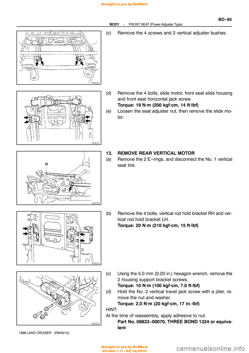
(c) Remove the 4 screws and 2 vertical adjuster bushes.
(d) Remove the 4 bolts, slide motor, front seat slide housing
and front seat horizontal jack screw.
Torque: 19 N·m (200 kgf·cm, 14 ft·lbf)
(e) Loosen the seat adjuster nut, then remove the slide mo- tor.
13. REMOVE REAR VERTICAL MOTOR
(a) Remove the 2 E −rings, and disconnect the No. 1 vertical
seat link.
(b) Remove the 4 bolts, vertical rod hold bracket RH and ver-
tical rod hold bracket LH.
Torque: 20 N·m (210 kgf·cm, 15 ft·lbf)
(c) Using the 5.0 mm (0.20 in.) hexagon wrench, remove the
2 housing support bracket screws.
Torque: 10 N·m (100 kgf·cm, 7.0 ft·lbf)
(d) Hold the No. 2 vertical travel jack screw with a plier, re- move the nut and washer.
Torque: 2.0 N·m (20 kgf·cm, 17 in.·lbf)
HINT:
At the time of reassembly, apply adhesive to nut.
Part No. 08833− 00070, THREE BOND 1324 or equiva-
lent
Brought to you by BirfMark
Brought to you by BirfMark
Version 1.11 - 03/16/2010
Page 355 of 1399

BR1CS−04
BR−22
−
BRAKE FRONT BRAKE PAD
1996 LAND CRUISER (RM451U)
REPLACEMENT
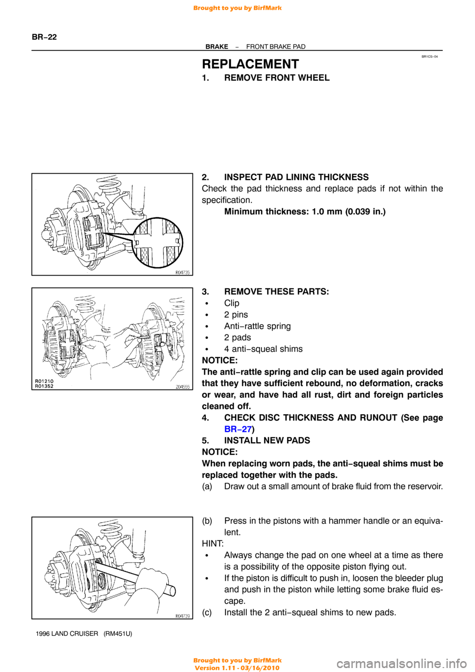
1. REMOVE FRONT WHEEL
2. INSPECT PAD LINING THICKNESS
Check the pad thickness and replace pads if not within the
specification. Minimum thickness: 1.0 mm (0.039 in.)
3. REMOVE THESE PARTS:
�Clip
�2 pins
�Anti−rattle spring
�2 pads
�4 anti−squeal shims
NOTICE:
The anti −rattle spring and clip can be used again provided
that they have sufficient rebound, no deformation, cracks
or wear, and have had all rust, dirt and foreign particles
cleaned off.
4. CHECK DISC THICKNESS AND RUNOUT (See page
BR−27 )
5. INSTALL NEW PADS
NOTICE:
When replacing worn pads, the anti −squeal shims must be
replaced together with the pads.
(a) Draw out a small amount of brake fluid from the reservoir.
(b) Press in the pistons with a hammer handle or an equiva- lent.
HINT:
�Always change the pad on one wheel at a time as there
is a possibility of the opposite piston flying out.
�If the piston is difficult to push in, loosen the bleeder plug
and push in the piston while letting some brake fluid es-
cape.
(c) Install the 2 anti−squeal shims to new pads.
Brought to you by BirfMark
Brought to you by BirfMark
Version 1.11 - 03/16/2010
Page 356 of 1399
−
BRAKE FRONT BRAKE PAD
BR−23
1996 LAND CRUISER (RM451U)
HINT:
Apply disc brake grease to both sides of the inner anti −squeal
shims (See page BR−21 ).
(d) Install the 2 pads.
HINT:
Apply disc brake grease to the caliper indicated by the arrows
(See page BR−33 ).
NOTICE:
Do not allow oil or grease to get on the rubbing face.
6. INSTALL ANTI −RATTLE SPRING AND 2 PINS
7. INSTALL CLIP
8. INSTALL FRONT WHEEL
9. CHECK THAT FLUID LEVEL IS AT MAX LINE
Brought to you by BirfMark
Brought to you by BirfMark
Version 1.11 - 03/16/2010
Page 358 of 1399
BR1CU−03
−
BRAKE FRONT BRAKE CALIPER
BR−25
1996 LAND CRUISER (RM451U)
REMOVAL
1. DISCONNECT FLEXIBLE HOSE
(a) Remove the union bolt and 2 gaskets from the caliper,
then disconnect the flexible hose from the caliper.
Torque: 30 N·m (310 kgf·cm, 22 ft·lbf)
(b) Use a container to catch the brake fluid as it drains out.
2. REMOVE CALIPER
Remove the 2 mounting bolts and caliper. Torque: 123 N·m (1,250 kgf·cm, 90 ft·lbf)
3. REMOVE THESE PARTS:
�Clip
�2 pins
�Anti−rattle spring
�2 pads
�4 anti−squeal shims
Brought to you by BirfMark
Brought to you by BirfMark
Version 1.11 - 03/16/2010