Page 1050 of 1399
 or more
H03286
RS−26
−
SUPPLEMENTAL RESTRAINT SYSTEM FRONT PASSENGER AIRBAG ASSEMBLY
1996 LAND CRUISER (RM451U)
1. AIRBAG DEPLOYMENT WHEN SCRAP")
AB0158
SSTBattery
SST
R13455
←→
10 m (33 ft) or more
H03286
RS−26
−
SUPPLEMENTAL RESTRAINT SYSTEM FRONT PASSENGER AIRBAG ASSEMBLY
1996 LAND CRUISER (RM451U)
1. AIRBAG DEPLOYMENT WHEN SCRAPPING VE-
HICLE
HINT:
Have a battery ready as the power source to deploy the airbag.
(a) Check functioning of the SST. (See page RS−11 )
(b) Disconnect the airbag connector. (1) Remove the glove compartment door.
(2) Remove the No.1 under cover.
NOTICE:
When handling the airbag connector , take care not to dam-
age the airbag wire harness.
(3) Pull up the connector.
(4) Disconnect the airbag connector.
(c) Install the SST. (1) Connect the SST connector to the front passengerairbag assembly connector.
SST 09082−00700
NOTICE:
To avoid damaging the SST connector and wire harness,
do not lock the secondary lock of the twin lock.
(2) Move the SST to at least 10 m (33 ft) away from the
front of the vehicle.
(3) Close all the doors and windows of the vehicle.
NOTICE:
Take care not to damage the SST wire harness.
(4) Connect the SST red clip to the battery positive (+)terminal and the black clip to the negative (+) termi-
nal.
(d) Deploy the airbag. (1) Confirm that no one is inside the vehicle or within 10
m (33 ft) area around the vehicle.
(2) Press the SST activation switch and deploy the air- bag.
HINT:
The airbag deploys simultaneously as the LED of the SST ac-
tivation switch lights up.
Brought to you by BirfMark
Brought to you by BirfMark
Version 1.11 - 03/16/2010
Page 1051 of 1399

(e) Dispose of the front passenger ai")
AB0163
Wire Harness
Diameter
Stripped Wire Harness Section
−
SUPPLEMENTAL RESTRAINT SYSTEM FRONT PASSENGER AIRBAG ASSEMBLY
RS−27
1996 LAND CRUISER (RM451U)
(e) Dispose of the front passenger airbag assembly.
CAUTION:
�The front passenger airbag assembly is very hot
when the airbag is deployed, so leave it alone for at
least 30 minutes after deployment.
�Use gloves and safety glasses when handling a front
passenger airbag assembly with deployed airbag.
�Always wash your hands with water after completing
the operation.
�Do not apply water, etc. to a front passenger airbag
assembly with deployed airbag.
(1) When scrapping a vehicle, deploy the airbag and scrap the vehicle with the front passenger airbag
assembly still installed.
(2) When moving a vehicle for scrapping which has a front passenger airbag assembly with deployed air-
bag, use gloves and safety glasses.
2. DEPLOYMENT WHEN DISPOSING OF FRONT PAS- SENGER AIRBAG ASSEMBLY ONLY
NOTICE:
�When disposing of the front passenger airbag assem-
bly only, never use the customer’s vehicle to deploy
the airbag.
�Be sure to follow the procedure given below when de-
ploying the airbag.
HINT:
Have a battery ready as the power source to deploy the airbag.
(a) Remove the front passenger airbag assembly. (See page RS−22 )
CAUTION:
�When removing the front passenger airbag assembly,
work must be started 90 seconds after the ignition
switch is turned to the ”LOCK” position and the nega-
tive (−) terminal cable is disconnected from the bat-
tery.
�Store the front passenger airbag assembly with the
airbag deployment side facing upward.
(b) Using a service− purpose wire harness for the vehicle, tie
down the front passenger airbag assembly to the tire.
Wire harness: Stripped wire harness section
1.25 mm
2 or more (0.0019 in.2 or more)
HINT:
To calculate the square of the stripped wire harness section: Square = 3.14 X (Diameter)
2 divided by 4
Brought to you by BirfMark
Brought to you by BirfMark
Version 1.11 - 03/16/2010
Page 1057 of 1399
RS0PE−01
−
SUPPLEMENTAL RESTRAINT SYSTEM AIRBAG SENSOR ASSEMBLY
RS−33
1996 LAND CRUISER (RM451U)
REMOVAL
NOTICE:
Do not open the cover or the case of the ECU and various
computers unless absolutely necessary.
(If the IC terminals are touched, the IC may be destroyed by
static electricity.)
1. REMOVE THESE PARTS:
(a) Transfer shirt knob
(b) Front console box
2. REMOVE AIRBAG SENSOR ASSEMBLY
(a) Disconnect the connector.
NOTICE:
Remove the connector with the sensor assembly installed.
(b) Using a torx wrench remove the 4 screws and the airbag sensor assembly.
Torx wrench: T40 (Part No. 09042 −00020 or locally
manufactured tool)
Brought to you by BirfMark
Brought to you by BirfMark
Version 1.11 - 03/16/2010
Page 1070 of 1399

REMOVAL
1. REMOVE FRONT WHEEL
2. REMOVE BRAKE CALIPER (See page BR−25 )
3. REMOVE FLANGE
(a) Using a")
SA1UB−01
SA2635
SST
−
SUSPENSION AND AXLE FRONT AXLE HUB
SA−7
1996 LAND CRUISER (RM451U)
REMOVAL
1. REMOVE FRONT WHEEL
2. REMOVE BRAKE CALIPER (See page BR−25 )
3. REMOVE FLANGE
(a) Using a screwdriver and hammer, remove the grease cap
from the flange.
(b) Using a snap ring expander, remove the snap ring.
(c) Loosen the 6 mounting nuts.
(d) Using a brass bar and hammer, tap on the 6 bolts heads and remove the 6 cone washers, plate washers and nuts.
(e) Remove the flange.
(f) Remove the gasket.
4. REMOVE AXLE HUB WITH DISC
(a) Using a screwdriver, release the lock washer.
(b) Using SST, remove the lock nut. SST 09607−60020
(c) Remove the lock washer.
(d) Using SST, remove the adjusting nut and thrust washer.
SST 09607−60020
(e) Remove the hub and disc together with the outer bearing.
5. REMOVE OIL SEAL AND INNER BEARING
(a) Using SST, remove the oil seal. SST 09308−00010
(b) Remove the inner bearing from the hub.
Brought to you by BirfMark
Brought to you by BirfMark
Version 1.11 - 03/16/2010
Page 1071 of 1399

REMOVAL
1. REMOVE FRONT WHEEL
2. REMOVE BRAKE CALIPER (See page BR−25 )
3. REMOVE FLANGE
(a) Using a")
SA1UB−01
SA2635
SST
−
SUSPENSION AND AXLE FRONT AXLE HUB
SA−7
1996 LAND CRUISER (RM451U)
REMOVAL
1. REMOVE FRONT WHEEL
2. REMOVE BRAKE CALIPER (See page BR−25 )
3. REMOVE FLANGE
(a) Using a screwdriver and hammer, remove the grease cap
from the flange.
(b) Using a snap ring expander, remove the snap ring.
(c) Loosen the 6 mounting nuts.
(d) Using a brass bar and hammer, tap on the 6 bolts heads and remove the 6 cone washers, plate washers and nuts.
(e) Remove the flange.
(f) Remove the gasket.
4. REMOVE AXLE HUB WITH DISC
(a) Using a screwdriver, release the lock washer.
(b) Using SST, remove the lock nut. SST 09607−60020
(c) Remove the lock washer.
(d) Using SST, remove the adjusting nut and thrust washer.
SST 09607−60020
(e) Remove the hub and disc together with the outer bearing.
5. REMOVE OIL SEAL AND INNER BEARING
(a) Using SST, remove the oil seal. SST 09308−00010
(b) Remove the inner bearing from the hub.
Brought to you by BirfMark
Brought to you by BirfMark
Version 1.11 - 03/16/2010
Page 1072 of 1399

INSTALLATION
1. PACK BEARINGS WITH MP GREASE
(a) Place MP grease on the palm of your hand")
SA1UD−01
SA2636
Grease
R04134
SST
−
SUSPENSION AND AXLE FRONT AXLE HUB
SA−9
1996 LAND CRUISER (RM451U)
INSTALLATION
1. PACK BEARINGS WITH MP GREASE
(a) Place MP grease on the palm of your hand.
(b) Pack grease into the bearing until the grease oozes out
from the other side.
(c) Do the same around the bearing circumference.
2. COAT INSIDE OF HUB WITH MP GREASE
3. INSTALL INNER BEARING AND OIL SEAL
(a) Place the inner bearing into the hub.
(b) Using SST, install a new oil seal into the hub. SST 09950−60020 (09951 −00910),
09950 −70010 (09951 −07150)
(c) Coat the oil seal lip with MP grease.
4. INSTALL AXLE HUB WITH DISC TO SPINDLE
(a) Place the axle hub with disc to the spindle.
(b) Install the outer bearing.
(c) Install the thrust washer.
5. ADJUST PRELOAD
(a) Using SST, torque the adjusting nut.
SST 09607−60020
Torque: 59 N·m (600 kgf·cm, 43 ft·lbf)
(b) Turn the hub right and left 2 or 3 times.
(c) Using SST, torque the adjusting nut.
SST 09607−60020
Torque: 59 N·m (600 kgf·cm, 43 ft·lbf)
(d) Loosen the nut until it can be turned by hand.
(e) Using SST, torque the adjusting nut again.
SST 09607−60020
Torque: 5.4 N·m (55 kgf·cm, 48 in.·lbf)
NOTICE:
Check that the bearing has no play.
(f) Using a spring tension gauge, measure the preload.
Preload (at starting):
28 − 56 N (2.9 − 5.7 kgf, 6.4 − 12.6 lbf)
6. INSTALL LOCK WASHER AND LOCK NUT
(a) Install a new lock washer and lock nut.
(b) Using SST, torque the lock nut. SST 09607−60020
Torque: 64 N·m (650 kgf·cm, 47 ft·lbf)
(c) Check that axle hub turns smoothly and that the bearing has no play.
(d) Using a spring tension gauge, check the preload. Preload (at starting):
28−56 N (2.9−5.7 kgf, 6.4−12.6 lbf)
If it is not within the specification, adjust it with the adjusting nut
after removing the lock washer and lock nut.
Brought to you by BirfMark
Brought to you by BirfMark
Version 1.11 - 03/16/2010
Page 1074 of 1399
SA1UE−01
−
SUSPENSION AND AXLE FRONT WHEEL HUB BOLT
SA−11
868
Author�: Date�:
1996 LAND CRUISER (RM451U)
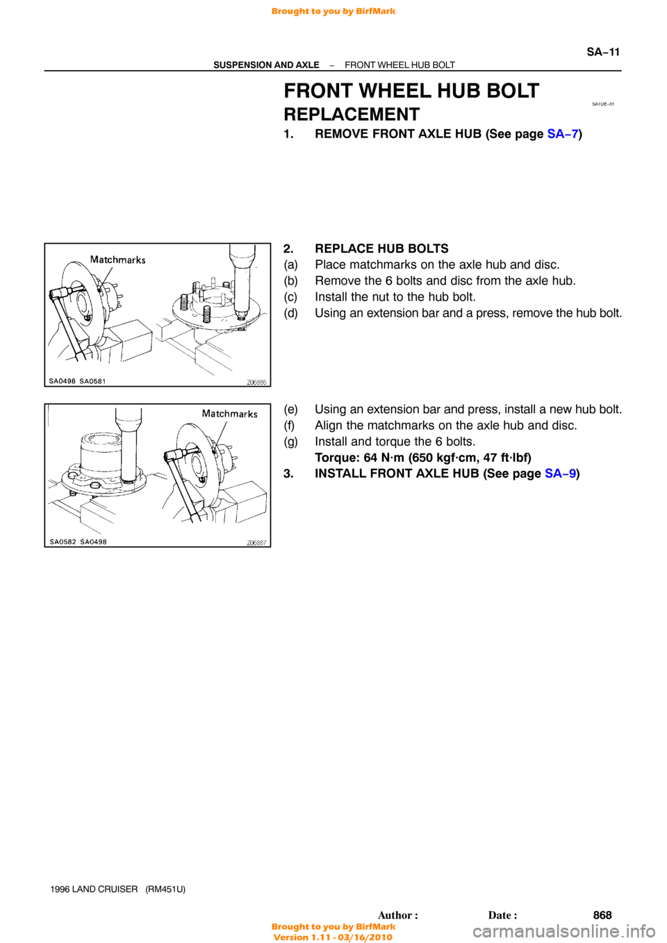
FRONT WHEEL HUB BOLT
REPLACEMENT
1. REMOVE FRONT AXLE HUB (See page SA−7 )
2. REPLACE HUB BOLTS
(a) Place matchmarks on the axle hub and disc.
(b) Remove the 6 bolts and disc from the axle hub.
(c) Install the nut to the hub bolt.
(d) Using an extension bar and a press, remove the hub bolt.
(e) Using an extension bar and press, install a new hub bolt.
(f) Align the matchmarks on the axle hub and disc.
(g) Install and torque the 6 bolts. Torque: 64 N·m (650 kgf·cm, 47 ft·lbf)
3. INSTALL FRONT AXLE HUB (See page SA−9)
Brought to you by BirfMark
Brought to you by BirfMark
Version 1.11 - 03/16/2010
Page 1076 of 1399

REMOVAL
1. REMOVE FRONT AXLE HUB (See page SA−7 )
2. REMOVE AB")
SA1UG−01
W00495
SA2644
SST
R08383
R13137
−
SUSPENSION AND AXLE STEERING KNUCKLE AND AXLE SHAFT
SA−13
1996 LAND CRUISER (RM451U)
REMOVAL
1. REMOVE FRONT AXLE HUB (See page SA−7 )
2. REMOVE ABS SPEED SENSOR
Remove the 2 bolts and disconnect the speed sensor from the
steering knuckle.
3. REMOVE DUST SEAL AND DUST COVER
Remove the 8 bolts, dust seal, dust cover and gasket.
4. REMOVE KNUCKLE SPINDLE
(a) Using a brass bar and hammer, tap the knuckle spindle of the steering knuckle.
(b) Remove the knuckle spindle and gasket.
5. REMOVE AXLE SHAFT
Position one flat part of the outer shaft upward and remove the
axle shaft.
6. DISCONNECT TIE ROD FROM KNUCKLE ARM
(a) Remove the cotter pin and nut.
(b) Using SST, disconnect the tie rod from the knuckle arm. SST 09611 −22012
7. REMOVE OIL SEAL SET
(a) Remove the 6 bolts from the end retainer.
(b) Remove these parts from the steering knuckle:
�Oil seal end retainer
�Felt dust seal
�Rubber seal
�Steel ring
8. REMOVE KNUCKLE ARM AND BEARING CAP
(a) Remove the 2 bolts and plate washers from the bearing cap.
(b) Remove the 4 nuts from the knuckle arm.
(c) Using a brass bar and hammer, tap on the 4 bolts heads and remove the 4 cone washers.
Brought to you by BirfMark
Brought to you by BirfMark
Version 1.11 - 03/16/2010

REMOVAL
NOTICE:
Do not open the cover or the case of the ECU and various
computers unless abso")