Page 1090 of 1399

REMOVAL
1. w/ DIFFERENTIAL LOCK:
BEFORE REMOVAL, SHIFT FRONT DIFFERENTIAL
TO LOCK
(a) Turn the")
SA1UM−03
FA2038
−
SUSPENSION AND AXLE FRONT DIFFERENTIAL CARRIER
SA−27
1996 LAND CRUISER (RM451U)
REMOVAL
1. w/ DIFFERENTIAL LOCK:
BEFORE REMOVAL, SHIFT FRONT DIFFERENTIAL
TO LOCK
(a) Turn the ignition switch to the ON position.
(b) Keep the center differential lock condition.
(c) Turn the differential lock control switch to the FR/RR posi-
tion and lock the front differential.
(d) Rotating the tires, check they are in the differential lock condition.
(e) Disconnect the cable from the negative terminal of the battery.
2. DRAIN DIFFERENTIAL OIL
3. REMOVE FRONT AXLE SHAFTS (See page SA−13)
4. REMOVE TIE ROD FROM KNUCKLE ARM (See page SA−13 )
5. REMOVE FRONT PROPELLER SHAFT (See page PR−3 )
6. w/ DIFFERENTIAL LOCK: DISCONNECT CONNECTORS AND TUBE
HINT:
�When connecting the tube of the harness side to the hose
of the actuator side, its depth of insertion is 15 mm (0.59
in.).
�Take care that water or equivalent does not adhere to the
connector and hose.
Brought to you by BirfMark
Brought to you by BirfMark
Version 1.11 - 03/16/2010
Page 1113 of 1399

REMOVAL
1. REMOVE FRONT WHEEL Torque:
Steel wheel: 147 N·m (1,500 kgf")
SA1US−01
SA2662
SA2663
R13152
SA−50
−
SUSPENSION AND AXLE COIL SPRING AND FRONT SHOCK ABSORBER
1996 LAND CRUISER (RM451U)
REMOVAL
1. REMOVE FRONT WHEEL Torque:
Steel wheel: 147 N·m (1,500 kgf·cm, 109 ft·lbf)
Aluminum wheel: 103 N·m (1,050 kgf·cm, 76 ft·lbf)
2. REMOVE FRONT SHOCK ABSORBER
(a) Jack up and support the axle housing.
(b) Hold the piston rod and remove the upper mounting nut. Torque: 69 N·m (700 kgf·cm, 51 ft·lbf)
(c) Hold the shock absorber and remove the lower mounting nut, shock absorber, cushions and retainers.
Torque: 69 N·m (700 kgf·cm, 51 ft·lbf)
3. DISCONNECT STABILIZER BAR FROM AXLE HOUS- ING (See page SA−60 )
4. REMOVE COIL SPRING
(a) Jack down and support axle housing.
(b) Using SST, compress the coil spring. SST 09727−30021
NOTICE:
Do not use an impact wrench. It will damage the SST.
(c) Remove the coil spring.
HINT:
Align the coil spring end with the lower seat and install the coil
spring.
5. REMOVE FOLLOW SPRING
Remove the 2 nuts and follow spring. Torque: 9.2 N·m (94 kgf·cm, 82 in.·lbf)
Brought to you by BirfMark
Brought to you by BirfMark
Version 1.11 - 03/16/2010
Page 1114 of 1399
SA1UT−01
FA0530
−
SUSPENSION AND AXLE COIL SPRING AND FRONT SHOCK ABSORBER
SA−51
1996 LAND CRUISER (RM451U)
INSPECTION
INSPECT SHOCK ABSORBER
Compress and extend the shock absorber rod and check that
there is abnormal resistance or unusual operation sounds.
If there is any abnormality, replace the shock absorber with a
new one.
NOTICE:
When discarding the shock absorber, use the following
procedure.
Brought to you by BirfMark
Brought to you by BirfMark
Version 1.11 - 03/16/2010
Page 1115 of 1399
SA1UU−01
SA2667
50 mm
(1.97 in.)30 mm
(1.18 in.)
SA−52
−
SUSPENSION AND AXLE COIL SPRING AND FRONT SHOCK ABSORBER
1996 LAND CRUISER (RM451U)
DISPOSAL
DISCARD SHOCK ABSORBER
Before discarding the shock absorber, drill a hole 2 − 3 mm
(0.079 − 0.118 in.) in diameter at the location shown in the il-
lustration to release the gas inside.
NOTICE:
When drilling, chips may fly out, work carefully. The gas is
colorless, odorless and non −poisonous.
Brought to you by BirfMark
Brought to you by BirfMark
Version 1.11 - 03/16/2010
Page 1117 of 1399
SA1UW−01
SA2675
SA2676
SA−54
−
SUSPENSION AND AXLE FRONT LATERAL CONTROL ROD
911
Author�: Date�:
1996 LAND CRUISER (RM451U)
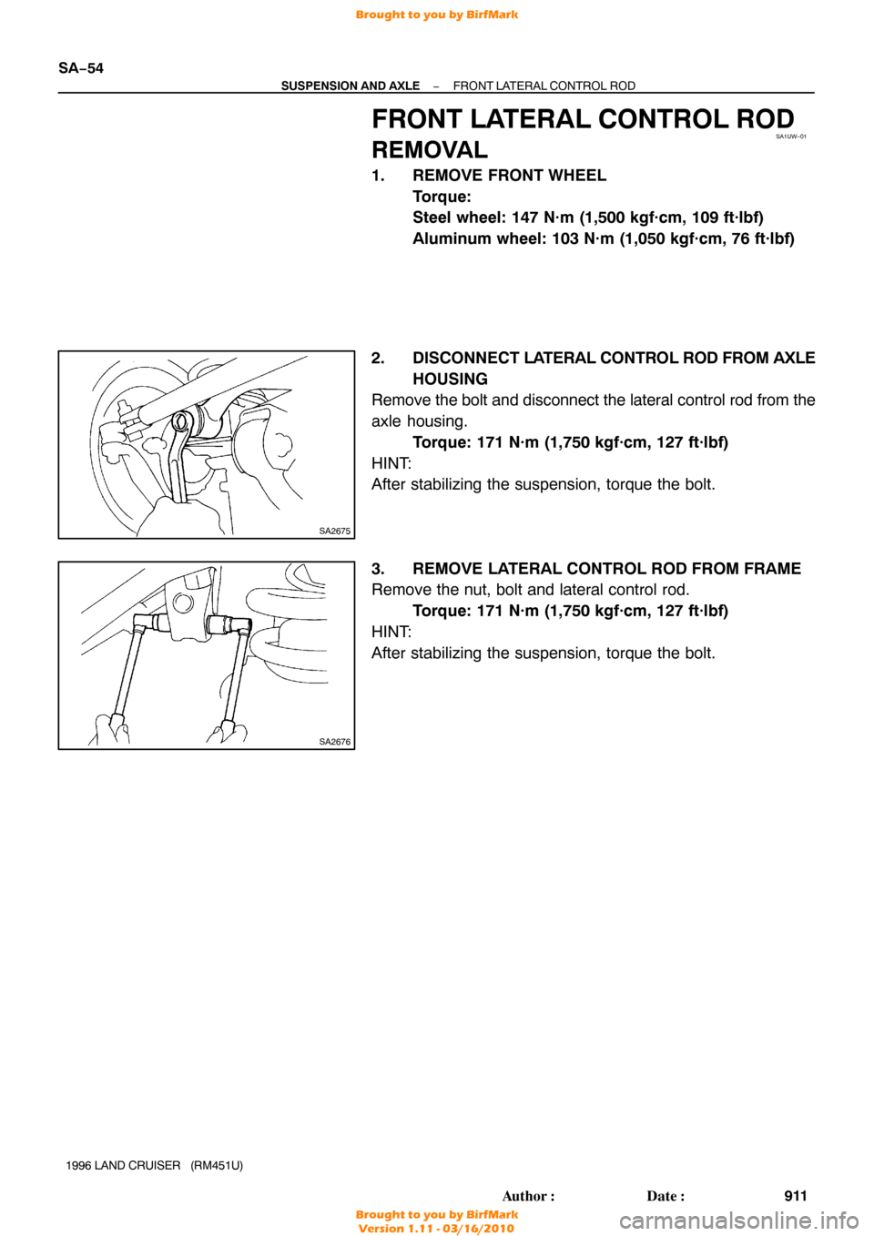
FRONT LATERAL CONTROL ROD
REMOVAL
1. REMOVE FRONT WHEEL
Torque:
Steel wheel: 147 N·m (1,500 kgf·cm, 109 ft·lbf)
Aluminum wheel: 103 N·m (1,050 kgf·cm, 76 ft·lbf)
2. DISCONNECT LA TERAL CONTROL ROD FROM AXLE
HOUSING
Remove the bolt and disconnect the lateral control rod from the
axle housing.
Torque: 171 N·m (1,750 kgf·cm, 127 ft·lbf)
HINT:
After stabilizing the suspension, torque the bolt.
3. REMOVE LATERAL CONTROL ROD FROM FRAME
Remove the nut, bolt and lateral control rod. Torque: 171 N·m (1,750 kgf·cm, 127 ft·lbf)
HINT:
After stabilizing the suspension, torque the bolt.
Brought to you by BirfMark
Brought to you by BirfMark
Version 1.11 - 03/16/2010
Page 1123 of 1399
SA1V2−01
R07756
R08394
R13153
Paint
SA−60
−
SUSPENSION AND AXLE FRONT STABILIZER BAR
917
Author�: Date�:
1996 LAND CRUISER (RM451U)
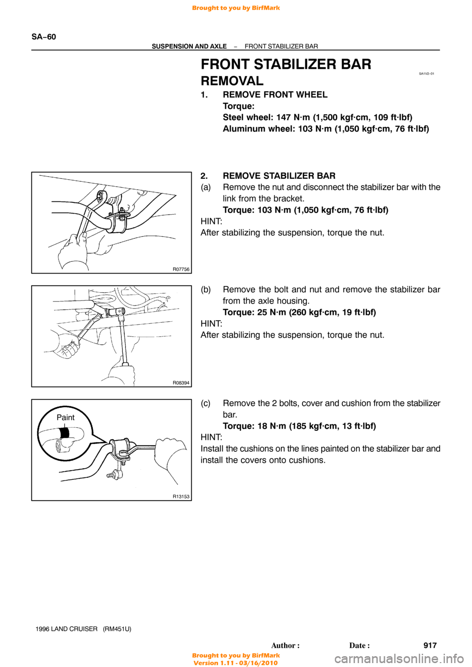
FRONT STABILIZER BAR
REMOVAL
1. REMOVE FRONT WHEEL
Torque:
Steel wheel: 147 N·m (1,500 kgf·cm, 109 ft·lbf)
Aluminum wheel: 103 N·m (1,050 kgf·cm, 76 ft·lbf)
2. REMOVE STABILIZER BAR
(a) Remove the nut and disconnect the stabilizer bar with the
link from the bracket.
Torque: 103 N·m (1,050 kgf·cm, 76 ft·lbf)
HINT:
After stabilizing the suspension, torque the nut.
(b) Remove the bolt and nut and remove the stabilizer bar from the axle housing.
Torque: 25 N·m (260 kgf·cm, 19 ft·lbf)
HINT:
After stabilizing the suspension, torque the nut.
(c) Remove the 2 bolts, cover and cushion from the stabilizer
bar.
Torque: 18 N·m (185 kgf·cm, 13 ft·lbf)
HINT:
Install the cushions on the lines painted on the stabilizer bar and
install the covers onto cushions.
Brought to you by BirfMark
Brought to you by BirfMark
Version 1.11 - 03/16/2010
Page 1136 of 1399
SA1VE−01
Z15218
SST
R13239
Z06901
SST
Z06902
SST
−
SUSPENSION AND AXLE REAR DIFFERENTIAL FRONT OIL SEAL
SA−73
1996 LAND CRUISER (RM451U)
REPLACEMENT
1. DRAIN DIFFERENTIAL OIL
2. DISCONNECT REAR PROPELLER SHAFT
(See page PR−3 )
3. REMOVE COMPANION FLANGE
(a) Using a chisel and hammer, loosen the staked part of the
nut.
(b) Using SST to hold the flange, remove the nut and plate washer.
SST 09330−00021
(c) Using SST, remove the companion flange. SST 09950−30010 (09951 −03010, 09953−03010,
09954 −03010, 09955 −03030, 09956−03020)
4. REMOVE OIL SEAL AND OIL SLINGER
(a) Using SST, remove the oil seal. SST 09308−10010
(b) Remove the oil slinger.
5. REMOVE FRONT BEARING
Using SST, remove the front bearing from the drive pinion. SST 09556−22010
Brought to you by BirfMark
Brought to you by BirfMark
Version 1.11 - 03/16/2010
Page 1165 of 1399

(6) Check the voltage between the terminals")
Z07254
M3 M4 M1 M2
Z07255
Wire Harness Side
SA−102
−
SUSPENSION AND AXLE DIFFERENTIAL LOCKING SYSTEM
959
Author�: Date�:
1996 LAND CRUISER (RM451U)
(6) Check the voltage between the terminals of the Diff.
lock ECU when switching the Diff. lock control
switch with the speedometer, registering approx. 8
km/h (5 mph) or more.
(7) Check that the indicator lights blink when center Diff. lock release mode is set.
Diff. lock is released for both the front wheels and
rear wheels at this time.
(8) Return the Diff. lock control switch to OFF.
(9) Stop the engine and lower the vehicle.
2. INSPECT DIFF. LOCK SYSTEM CIRCUIT
(a) Inspect the system circuit with connector disconnected. Disconnect the connector from the Diff. lock ECU and in-
spect the connector on the wire harness side, as shown
in the chart.
Trouble Part/
Terminals (Symbols)ConditionSpecified V alue
Rear diff. lock actuator/
1 (M2) − 3 (M1)−Less than 100 Ω
Front diff. lock actuator/
5 (M4) − 7 (M1)−Less than 100 Ω
Body ground/
13 (GND) − Body ground−Continuity
Vehicle speed sensor/
4(SPD) − Body groundVehicle moving slowly1 pulse each 40 cm (15.75 in.)
Brought to you by BirfMark
Brought to you by BirfMark
Version 1.11 - 03/16/2010

INSPECTION
INSPECT SHOCK ABSORBER
Compress and extend the shock absorber rod and che")
30 mm
(1.18 in.)
SA−52
−
SUSPENSION AND AXLE COIL SPRING AND FRONT SHOCK ABSORBER
1996 LAND CRUISER (RM451U)
DISPOSAL
DISCARD SHOCK ABSORBER
Before discarding")

REPLACEMENT
1. DRAIN DIFFERENTIAL OIL
2. DISCONNECT REA")