Page 1364 of 1399
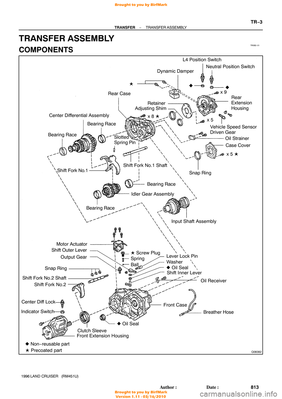
TR0B2−01
Q08382
Dynamic Damper
Rear Case �
Vehicle Speed Sensor
Driven Gear
Center Differential Assembly
Bearing Race
Bearing Race L4 Position Switch
Neutral Position Switch
x 9
�
Rear
Extension
Housing
Oil Strainer Case Cover
x 5 �
Shift Fork No.1
Bearing Race
Idler Gear Assembly
Motor Actuator
Shift Outer Lever
Output Gear
Snap Ring
Shift Fork No.2 Shaft Shift Fork No.2
Center Diff Lock
Indicator Switch
Lever Lock Pin
Washer
� Oil Seal
Shift Inner Lever
Oil Receiver
Breather Hose
Front Case Snap Ring
Shift Fork No.1 Shaft
� Non− reusable part
� Precoated part Front Extension Housing
Clutch Sleeve �
Oil Seal
Bearing Race
�
Slotted
Spring Pin
Input Shaft Assemblyx 5
x 8 �
Retainer
Adjusting Shim
� Screw Plug
Spring
Ball
−
TRANSFER TRANSFER ASSEMBLY
TR−3
813
Author�: Date�:
1996 LAND CRUISER (RM451U)
TRANSFER ASSEMBLY
COMPONENTS
Brought to you by BirfMark
Brought to you by BirfMark
Version 1.11 - 03/16/2010
Page 1365 of 1399

DISASSEMBLY
1. REMOVE BREATHER HOSE
2. REMOVE DYNAMIC DAMPER
Remove the 2 bolts and dynamic damper.
HIN")
TR0CM−01
Q07105
Q07124
FIPG
TR−4
−
TRANSFER TRANSFER ASSEMBLY
1996 LAND CRUISER (RM451U)
DISASSEMBLY
1. REMOVE BREATHER HOSE
2. REMOVE DYNAMIC DAMPER
Remove the 2 bolts and dynamic damper.
HINT:
At the time of reassembly, apply adhesive to the bolt threads. Adhesive: Part No.08833 −00070, THREE BOND 1324
or equivalent
Torque: 37 N·m (380 kgf·cm, 27 ft·lbf)
3. REMOVE MOTOR ACTUATOR
Remove the 4 bolts and motor actuator.
HINT:
At the time of reassembly, please refer to the following items.
�Set the motor actuator in differential lock condition.
�Apply FIPG to the front case.
FIPG: Part No. 08826−00090, THREE BOND 1281 or
equivalent
Torque: 18 N·m (185 kgf·cm, 13 ft·lbf)
4. REMOVE OUTPUT GEAR FROM FRONT CASE
HINT:
At the timie of reassembly apply gear oil to the output gear.
NOTICE:
At the time of reassembly, do not turn the output gear.
5. REMOVE SCREW PLUG, SPRING AND BALL
(a) Using a torx socket wrench (T40), remove the screw plug.
HINT:
At the time of reassembly, apply liquid sealer to the screw plug. Sealant: Part No.08833−00080, THREE BOND 1344,
LOCTITE 242 or equivalent
Torque:19 N·m (190 kgf·cm, 14 ft·lbf)
(b) Using a magnetic finger, remove the spring and ball.
Brought to you by BirfMark
Brought to you by BirfMark
Version 1.11 - 03/16/2010
Page 1368 of 1399

Thickness:
Dimension C + (0. 014 − 0.039 mm, 0.0006 − 0.0015 in.)
(i) From the following table, sele")
Q07126
FIPG
Q08404
FIPG
A
−
TRANSFER TRANSFER ASSEMBLY
TR−7
1996 LAND CRUISER (RM451U)
Thickness:
Dimension C + (0. 014 − 0.039 mm, 0.0006 − 0.0015 in.)
(i) From the following table, select a shim so that its thick-
ness is within the range of the calculation.
MarkThickness mm (in.)MarkThickness mm (in.)
B0.30 (0.0118)H1.80 (0.0709)
C0.45 (0.0177)J2.00 (0.0787)
D1.00 (0.0394)K2.20 (0.0866)
E1.20 (0.0472)L2.40 (0.0945)
F1.40 (0.0551)M2.60 (0.1024)
G1.60 (0.0630)N0.55 (0.0216)
13. REMOVE OIL STRAINER FROM REAR CASE
Remove the 2 set bolts and oil strainer.Torque: 4.9 N·m (50 kgf·cm, 43 in.·lbf)
14. REMOVE CASE COVER
(a) Remove the 5 bolts.
HINT:
At the time of reassembly, apply liquid sealer to the bolt threads.
Sealant: Part No.08833−00080, THREE BOND 1344,
LOCTITE 242 or equivalent
Torque: 37 N·m (380 kgf·cm, 27 ft·lbf)
(b) Using a brass bar and hammer, tap the case cover and remove it.
HINT:
At the time of reassembly, apply FIPG to the rear case. FIPG: Part No. 08826−00090, THREE BOND 1281 or
equivalent
15. SEPARATE FRONT CASE AND REAR CASE
(a) Using a snap ring expander, remove the snap ring from the rear case.
(b) Remove the 8 bolts.
HINT:
At the time of reassembly, apply liquid sealer to the ”A” bolt
threads. Sealant: Part No.08833 −00080, THREE BOND 1344,
LOCTITE 242 or equivalent
Torque:37 N·m (380 kgf·cm, 27 ft·lbf)
(c) Using a brass bar and hammer, tap the rear case and sep-
arate it.
HINT:
At the time of reassembly, apply FIPG to the front case.
Brought to you by BirfMark
Brought to you by BirfMark
Version 1.11 - 03/16/2010
Page 1369 of 1399

FIPG: Part No. 08826−00090, THREE BOND 1281 or
equival")
TF0854
TF0986
TF0857
Q07130
RemovalInstallation
Socket Wrench Socket Wrench
TR−8
−
TRANSFER TRANSFER ASSEMBLY
1996 LAND CRUISER (RM451U)
FIPG: Part No. 08826−00090, THREE BOND 1281 or
equivalent
16. REMOVE 2 BEARING RACES FROM REAR CASE
17. REMOVE INPUT SHAFT ASSEMBLY
Using a plastic hammer, remove the input shaft assembly.
18. REMOVE IDLER GEAR ASSEMBLY, CENTER DIFFER-
ENTIAL ASSEMBLY, SHIFT FORK NO.1 AND SHIFT
FORK NO.1 SHAFT FROM FRONT CASE
19. SEPARATE SHIFT FORK NO.1 AND SHIFT FORK NO.1 SHAFT
(a) Using a pin punch and hammer, drive out the slotted spring pin.
(b) Separate the shift fork No.1 and shift fork No.1 shaft.
20. REMOVE SHIFT OUTER LEVER AND INNER LEVER
(a) Remove the nut and washer from the shift outer lever. Torque: 12 N·m (120 kgf·cm, 9 ft·lbf)
(b) Using a brass bar, hammer and socket wrench, tap out the lever lock pin.
(c) Remove the shift outer lever, washer and inner lever from
the front case.
21. REMOVE OIL RECEIVER FROM FRONT CASE
Remove the bolt and oil receiver. Torque: 12 N·m (120 kgf·cm, 9 ft·lbf)
Brought to you by BirfMark
Brought to you by BirfMark
Version 1.11 - 03/16/2010
Page 1371 of 1399
TF0862
SST
TR0CN−01
TF0863
SST
TF0864
SST
SST
TR−10
−
TRANSFER TRANSFER ASSEMBLY
1996 LAND CRUISER (RM451U)
REPLACEMENT
1. REPLACE SHIFT LEVER OIL SEAL
(a) Using a screwdriver, pry out the oil seal.
(b) Using SST and a hammer, drive in a new oil seal. SST 0608−00081, 09950 −70010 (09951−07150)
2. REPLACE INPUT SHAFT OIL SEAL
(a) Using SST and a hammer, drive out the oil seal. SST 09316−60011 (09316 −00011)
(b) Using SST and a hammer, drive in a new oil seal. SST 09316−60011 (09316 −00011, 09316−00031)
Brought to you by BirfMark
Brought to you by BirfMark
Version 1.11 - 03/16/2010
Page 1372 of 1399
TR0B4−01
−
TRANSFER TRANSFER ASSEMBLY
TR−11
1996 LAND CRUISER (RM451U)
REASSEMBLY
Reassembly is in the reverse order of disassembly (See page TR−4 ).
HINT:
Coat all of the sliding and rotating surfaces with gear oil before assem\
bly.
Brought to you by BirfMark
Brought to you by BirfMark
Version 1.11 - 03/16/2010
Page 1375 of 1399

REASSEMBLY
HINT:
Coat all of the sliding and rotating surfaces with gear oil before
assembly.
1. INSTALL FRONT BALL BEAR")
TR0B7−01
Q00533
TR−14
−
TRANSFER INPUT SHAFT
1996 LAND CRUISER (RM451U)
REASSEMBLY
HINT:
Coat all of the sliding and rotating surfaces with gear oil before
assembly.
1. INSTALL FRONT BALL BEARING
Using SST and a press, install a new front ball bearing. SST 09527−30010
2. INSTALL INPUT GEAR
(a) Using a press, install the input gear.
(b) Select a snap ring that will allow minimum axial play.
MarkThickness mm (in.)MarkThickness mm (in.)
A2.00 (0.0787)F2.50 (0.0984)
B2.10 (0.0827)G2.60 (0.1024)
C2.20 (0.0866)H2.70 (0.1063)
D2.30 (0.0906)J2.80 (0.1 102)
E2.40 (0.0945)−−
(c) Using a snap ring expander, install a new snap ring.
3. INSTALL REAR BALL BEARING
(a) Using SST and a press, install a new rear ball bearing.
SST 09316−60011 (09316 −00031)
(b) Select a snap ring that will allow minimum axial play.
MarkThickness mm (in.)
A2.00 (0.0787)
B2.10 (0.0827)
C2.20 (0.0866)
D2.30 (0.0906)
E2.40 (0.0945)
(c) Using a snap ring expander, install a new snap ring.
Brought to you by BirfMark
Brought to you by BirfMark
Version 1.11 - 03/16/2010
Page 1378 of 1399
TR0BA−01
TF0893
SST
Q00538
TF0896
SST
−
TRANSFER IDLER GEAR
TR−17
1996 LAND CRUISER (RM451U)
REASSEMBLY
HINT:
Coat all of the sliding and rotating surfaces with gear oil before
assembly.
1. INSTALL FRONT TAPER ROLLER BEARING
Using SST and a press, install the front taper roller bearing.
SST 09316−60011 (09316 −00011, 09316−00031)
2. INSTALL HIGH AND LOW CLUTCH SLEEVE
HINT:
Make sure to install the high and low clutch sleeve in the correct
direction.
3. INSTALL NEEDLE ROLLER BEARING AND IDLER LOW GEAR TO IDLER GEAR
(a) Apply gear oil to the needle roller bearing.
(b) Install the needle roller bearing and idler low gear.
4. INSTALL REAR TAPER ROLLER BEARING
Using SST and a press, install the rear taper roller bearing. SST 09316−60011 (09316 −00011, 09316−00071)
5. INSPECT IDLER LOW GEAR RADIAL AND THRUST CLEARANCE
(See page TR−16 )
Brought to you by BirfMark
Brought to you by BirfMark
Version 1.11 - 03/16/2010

REPLACEMENT
1. REPLACE SHIFT LEVER OIL SEAL
(a) Using a screwdriver, pry out the oil")

REASSEMBLY
Reassembly is in the reverse order of disassembly (See page TR−4 ).
HINT:
Coat all of the sliding and rotat")

REASSEMBLY
HINT:
Coat all of the sliding and rotating surfaces with gear oil before
assembly.
1. IN")