Page 1258 of 1399
Z15498
PS GearClosed
SST PS Vane
Pump
Oil
Reservoir
−
STEERING POWER STEERING FLUID
SR−5
1996 LAND CRUISER (RM451U)
2. CHECK STEERING FLUID PRESSURE
(a) Disconnect the pressure feed tube from the PS vane
pump (See page SR−23).
(b) Connect SST over 2 new gaskets, as shown below. SST 09640 −10010 (09641 −01010, 09641 −01030,
09641 −01060)
NOTICE:
Check that the valve of the SST is in the open position.
(c) Bleed the power steering system (See page SR−3).
(d) Start the engine and run it at idle.
(e) Turn the steering wheel from lock to lock several times to
boost fluid temperature.
Fluid temperature: 80° C (176°F)
(f) With the engine idling, close the valve of the SST and ob-
serve the reading on the SST.
Minimum fluid pressure:
9,316kPa (95 kgf/cm
2, 1,351 psi)
NOTICE:
�Do not keep the valve closed for more than 10 se-
conds.
�Do not let the fluid temperature become too high.
Brought to you by BirfMark
Brought to you by BirfMark
Version 1.11 - 03/16/2010
Page 1259 of 1399
Z15499
PS GearSSTPS Vane
Pump
Oil
Reservoir
Open
Z15500
PS Gear
SSTPS Vane
Pump
Oil
Reservoir
Open
Lock Position
SR−6
−
STEERING POWER STEERING FLUID
1996 LAND CRUISER (RM451U)
(g) With the engine idling, open the valve fully.
(h) Measure the fluid pressure at engine speeds of 1,000 rpm
and 3,000 rpm.
Difference fluid pressure:
490 kPa (5 kgf/cm
2, 71 psi) or less
NOTICE:
Do not turn the steering wheel.
(i) With the engine idling and valve fully opened, turn the steering wheel to full lock.
Minimum fluid pressure:
9,316 kPa (95 kgf/cm
2, 1,351 psi)
NOTICE:
�Do not maintain lock position for more than 10 se-
conds.
�Do not let the fluid temperature become too high.
(j) Disconnect the SST.
(k) Connect the pressure feed tube (See page SR−32).
(l) Bleed the power steering system (See page SR−3).
Brought to you by BirfMark
Brought to you by BirfMark
Version 1.11 - 03/16/2010
Page 1263 of 1399

SR−12
−
STEERING TILT STEERING COLUMN
1996 LAND CRUISER (RM451U)
3. REMOVE INSTRUMENT LOWER FINISH PANEL
(a) Disconnect the hood lock control cable and fuel lid control
cable.
(b) Remove the 4 panel set screws.
4. REMOVE NO.2 HEATER TO REGISTER DUCT
5. REMOVE UPPER AND LOWER COLUMN COVERS
Remove the 5 screws.
6. REMOVE COMBINATION SWITCH WITH SPIRAL CABLE
(a) Disconnect the 2 connectors.
(b) Disconnect the airbag connector.
(c) Remove the 4 screws.
NOTICE:
Do not disassemble the cable or apply oil to it.
7. REMOVE 4 COLUMN HOLE COVER SET BOLTS
8. REMOVE LINK JOINT PROTECTOR
Remove the 2 bolts.
9. DISCONNECT SLIDING YOKE SUB−ASSEMBLY
(a) Place matchmarks on the yoke sub −assembly and worm
gear valve body shaft.
(b) Loosen bolt A and remove bolt B.
10. REMOVE SLIDING YOKE SUB−ASSEMBLY
Remove the bolt A.
11. REMOVE TILT STEERING COLUMN ASSEMBLY
(a) Disconnect the 3 connectors.
(b) Remove the 2 column assembly set nuts and 2 set bolts.
Brought to you by BirfMark
Brought to you by BirfMark
Version 1.11 - 03/16/2010
Page 1278 of 1399

SR16I−02
R15644
Vane Pump ShaftFront
Housing Bushing
Micrometer
Caliper
Gauge
N00372
Height Thickness
Length
R10282
Feeler Gauge
R15645Inscribed Mark
−
STEERING POWER STEERING VANE PUMP
SR−27
1996 LAND CRUISER (RM451U)
INSPECTION
1. CHECK OIL CLEARANCE BETWEEN VANE PUMP
SHAFT AND BUSHING
Using a micrometer and caliper gauge, measure the oil clear-
ance. Standard clearance:
0.03 − 0.05 mm (0.0012 − 0.0020 in.)
Maximum clearance: 0.07 mm (0.0028 in.)
If it is more than maximum, replace the front housing and vane
pump shaft.
2. INSPECT V ANE PUMP ROTOR AND 10 VANE PLATES
(a) Using a micrometer, measure the height, thickness and length of the plate.
Minimum height: 8.6 mm (0.339 in.)
Minimum thickness: 1.397 mm (0.0550 in.)
Minimum length: 14.991 mm (0.5902 in.)
(b) Using a feeler gauge, measure the clearance between the rotor groove and plate.
Maximum clearance: 0.033 mm (0.0013 in.)
If more than maximum, replace the plate and/or rotor with one
having the mark equivalent to the mark stamped on the cam
ring. Inscribed mark
Vane pump rotor: 1, 2, or None
Cam ring: 2, 3, or 4
Brought to you by BirfMark
Brought to you by BirfMark
Version 1.11 - 03/16/2010
Page 1280 of 1399

SR4528
Tape
Screwdriver
R13761REMOVEINSTALL
Press
Bearing
R08077
Press
SST Oil Seal
W03071
Socket
Wrench
Press
A
A 3.4 mm
(+ 3mm)
−
STEERING POWER STEERING VANE PUMP
SR−29
1996 LAND CRUISER (RM451U)
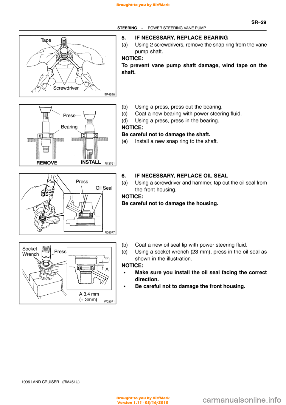
5. IF NECESSARY, REPLACE BEARING
(a) Using 2 screwdrivers, remove the snap ring from the vane
pump shaft.
NOTICE:
To prevent vane pump shaft damage, wind tape on the
shaft.
(b) Using a press, press out the bearing.
(c) Coat a new bearing with power steering fluid.
(d) Using a press, press in the bearing.
NOTICE:
Be careful not to damage the shaft.
(e) Install a new snap ring to the shaft.
6. IF NECESSARY, REPLACE OIL SEAL
(a) Using a screwdriver and hammer, tap out the oil seal from
the front housing.
NOTICE:
Be careful not to damage the housing.
(b) Coat a new oil seal lip with power steering fluid.
(c) Using a socket wrench (23 mm), press in the oil seal as shown in the illustration.
NOTICE:
�Make sure you install the oil seal facing the correct
direction.
�Be careful not to damage the front housing.
Brought to you by BirfMark
Brought to you by BirfMark
Version 1.11 - 03/16/2010
Page 1283 of 1399

SR16J−01
R08080
Socket
WrenchPress
R08098
Inscribed Mark
R08081
Round End
SR−30
−
STEERING POWER STEERING VANE PUMP
1996 LAND CRUISER (RM451U)
REASSEMBLY
NOTICE:
When using a vise, do not overtighten it.
1. COAT WITH POWER STEERING FLUID
(See page SR−21 )
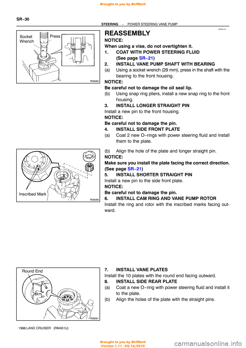
2. INSTALL VANE PUMP SHAFT WITH BEARING
(a) Using a socket wrench (29 mm), press in the shaft with the bearing to the front housing.
NOTICE:
Be careful not to damage the oil seal lip.
(b) Using snap ring pliers, install a new snap ring to the front housing.
3. INSTALL LONGER STRAIGHT PIN
Install a new pin to the front housing.
NOTICE:
Be careful not to damage the pin.
4. INSTALL SIDE FRONT PLATE
(a) Coat 2 new O−rings with power steering fluid and install them to the plate.
(b) Align the hole of the plate and longer straight pin.
NOTICE:
Make sure you install the plate facing the correct direction.
(See page SR−21 )
5. INSTALL SHORTER STRAIGHT PIN
Install a new pin to the side front plate.
NOTICE:
Be careful not to damage the pin.
6. INSTALL CAM RING AND VANE PUMP ROTOR
Install the ring and rotor with the inscribed marks facing out-
ward.
7. INSTALL VANE PLATES
Install the 10 plates with the round end facing outward.
8. INSTALL SIDE REAR PLATE
(a) Coat a new O −ring with power steering fluid and install it
to the plate.
(b) Align the holes of the plate with the straight pins.
Brought to you by BirfMark
Brought to you by BirfMark
Version 1.11 - 03/16/2010
Page 1291 of 1399

SR16O−01
Z14503
Dial Indicator30 mm
(1.18 in.)
Z14504
Dial Indicator
Z10600
Z06211
SR−38
−
STEERING POWER STEERING GEAR
1996 LAND CRUISER (RM451U)
INSPECTION
NOTICE:
When using a vise, do not overtighten it.
1. INSPECT BALL CLEARANCE
Using a dial indicator, check the ball clearance. Move the worm
gear up and down. Maximum clearance: 0.15 mm (0.0059 in.)
2. INSPECT CROSS SHAFT ADJUSTING SCREW THRUST CLEARANCE
Using a dial indicator, measure the thrust clearance. Standard clearance: 0.03 − 0.05 (0.0012 − 0.0020 in.)
3. IF NECESSARY, ADJUST CROSS SHAFT ADJUSTING SCREW THRUST CLEARANCE
(a) Using a chisel and hammer, unstake the No.1 lock nut.
(b) Using SST, remove the No.1 lock nut. SST 09630−00014 (09631 −00051)
(c) Using a screwdriver, adjust the adjusting screw for correct thrust clearance.
(d) Using the SST, tighten a new lock nut.
(e) Using a chisel and hammer, stake the lock nut.
4. IF NECESSARY, REPLACE OIL SEAL, METAL SPACER AND TEFLON RING
(a) Using a screwdriver, pry out the oil seal from the gear
housing.
(b) Using snap ring pliers, remove the snap ring from the gear
housing.
(c) Remove the metal spacer, teflon ring and O −ring from the
gear housing.
Brought to you by BirfMark
Brought to you by BirfMark
Version 1.11 - 03/16/2010
Page 1292 of 1399

SR2804
−
STEERING POWER STEERING GEAR
SR−39
1996 LAND CRUISER (RM451U)
(d) Coat a new O− ring and metal spacer with power steering
fluid and install them.
(e) Using snap ring pliers, install a new snap ring.
(f) Coat a new teflon ring with power steering fluid.
(g) Form a teflon ring into a heart shape and install it with
hand.
(h) Using SST, form the teflon ring.
SST 09630−00014 (09631 −00121)
NOTICE:
The teflon ring must be squeezed before inserting the
cross shaft or damage will result.
(i) Coat a new oil seal with power steering fluid.
(j) Using SST, press in the oil seal to the gear housing. SST 09950−60010 (09951 −00340, 09951−00450)
09950 −70010 (09951 −07200)
NOTICE:
Make sure you install the oil seal facing the correct direc-
tion.
5. IF NECESSARY, REPLACE TEFLON RING AND O −
RING
(a) Using a screwdriver, remove the teflon ring and O −ring
from the worm gear valve body assembly.
NOTICE:
Be careful not to damage the worm gear valve body assem-
bly.
(b) Coat a new O −ring with power steering fluid and install it.
(c) Expand a new teflon ring with your fingers.
NOTICE:
Be careful not to overexpand the teflon ring.
(d) Install the teflon ring.
(e) Coat the teflon ring with power steering fluid and snug it down with piston ring compressor for 5 − 7 minutes.
Brought to you by BirfMark
Brought to you by BirfMark
Version 1.11 - 03/16/2010