Page 1382 of 1399

TR0BD−01
Q07115
SSTStamp
TF1012
TF0913
TF0917
−
TRANSFER CENTER DIFFERENTIAL
TR−21
1996 LAND CRUISER (RM451U)
REASSEMBLY
HINT:
Coat all of the sliding and rotating surfaces with gear oil before
assembly.
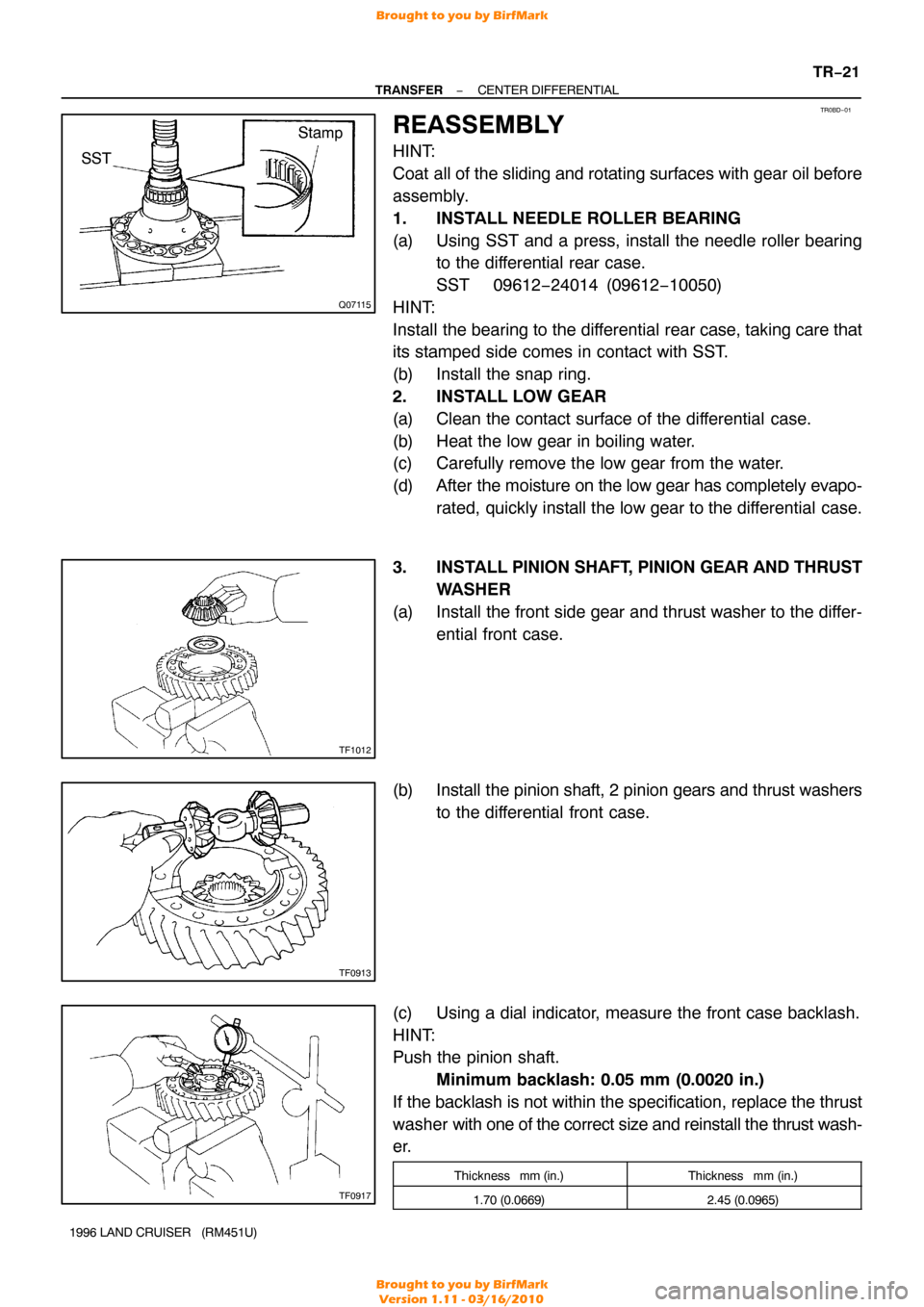
1. INSTALL NEEDLE ROLLER BEARING
(a) Using SST and a press, install the needle roller bearing
to the differential rear case.
SST 09612−24014 (09612 −10050)
HINT:
Install the bearing to the differential rear case, taking care that
its stamped side comes in contact with SST.
(b) Install the snap ring.
2. INSTALL LOW GEAR
(a) Clean the contact surface of the differential case.
(b) Heat the low gear in boiling water.
(c) Carefully remove the low gear from the water.
(d) After the moisture on the low gear has completely evapo- rated, quickly install the low gear to the differential case.
3. INSTALL PINION SHAFT, PINION GEAR AND THRUST
WASHER
(a) Install the front side gear and thrust washer to the differ- ential front case.
(b) Install the pinion shaft, 2 pinion gears and thrust washers
to the differential front case.
(c) Using a dial indicator, measure the front case backlash.
HINT:
Push the pinion shaft. Minimum backlash: 0.05 mm (0.0020 in.)
If the backlash is not within the specification, replace the thrust
washer with one of the correct size and reinstall the thrust wash-
er.
Thickness mm (in.)Thickness mm (in.)
1.70 (0.0669)2.45 (0.0965)
Brought to you by BirfMark
Brought to you by BirfMark
Version 1.11 - 03/16/2010
Page 1384 of 1399

Q00546
SST
Q00555
Q00539
SSTSST
Q00540
SST
SST
TF0931
−
TRANSFER CENTER DIFFERENTIAL
TR−23
1996 LAND CRUISER (RM451U)
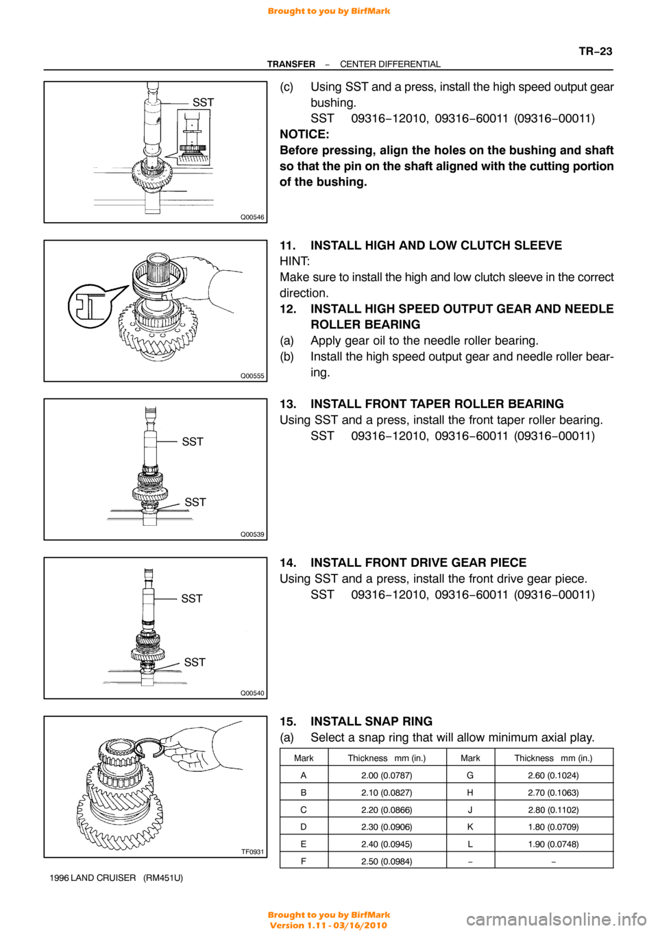
(c) Using SST and a press, install the high speed output gear
bushing.
SST 09316−12010, 09316 −60011 (09316−00011)
NOTICE:
Before pressing, align the holes on the bushing and shaft
so that the pin on the shaft aligned with the cutting portion
of the bushing.
11. INSTALL HIGH AND LOW CLUTCH SLEEVE
HINT:
Make sure to install the high and low clutch sleeve in the correct
direction.
12. INSTALL HIGH SPEED OUTPUT GEAR AND NEEDLE ROLLER BEARING
(a) Apply gear oil to the needle roller bearing.
(b) Install the high speed output gear and needle roller bear-
ing.
13. INSTALL FRONT TAPER ROLLER BEARING
Using SST and a press, install the front taper roller bearing. SST 09316−12010, 09316 −60011 (09316−00011)
14. INSTALL FRONT DRIVE GEAR PIECE
Using SST and a press, install the front drive gear piece. SST 09316−12010, 09316 −60011 (09316−00011)
15. INSTALL SNAP RING
(a) Select a snap ring that will allow minimum axial play.
MarkThickness mm (in.)MarkThickness mm (in.)
A2.00 (0.0787)G2.60 (0.1024)
B2.10 (0.0827)H2.70 (0.1063)
C2.20 (0.0866)J2.80 (0.1 102)
D2.30 (0.0906)K1.80 (0.0709)
E2.40 (0.0945)L1.90 (0.0748)
F2.50 (0.0984)−−
Brought to you by BirfMark
Brought to you by BirfMark
Version 1.11 - 03/16/2010
Page 1386 of 1399
TR0BE−01
Z18836
Front Output Shaft�
Dust Deflector
� Oil Seal Housing Ball Bearing
�
Snap Ring Drive Clutch Hub
�
Snap Ring
� Snap Ring
−
TRANSFER FRONT EXTENSION HOUSING
TR−25
835
Author�: Date�:
1996 LAND CRUISER (RM451U)
FRONT EXTENSION HOUSING
COMPONENTS
Brought to you by BirfMark
Brought to you by BirfMark
Version 1.11 - 03/16/2010
Page 1387 of 1399
TR0BF−01
Q07133
SST
TF0938
TF0940
SST
TR−26
−
TRANSFER FRONT EXTENSION HOUSING
1996 LAND CRUISER (RM451U)
DISASSEMBLY
1. REMOVE DRIVE CLUTCH HUB
(a) Using a snap ring expander, remove the snap ring.
(b) Using SST, remove the drive clutch hub. SST 09950−40010
2. REMOVE FRONT OUTPUT SHAFT
Using a plastic hammer, drive out the front output shaft.
3. REMOVE DUST DEFLECTOR
(a) Using SST and a press, remove the dust deflector. SST 09950−00020
(b) Using a screwdriver and hammer, tap the dust deflector
and remove it from the extension housing.
4. REMOVE OIL SEAL
Using a screwdriver, pry out the oil seal from the front extension
housing.
5. REMOVE BALL BEARING
(a) Using a screwdriver, remove the snap ring.
(b) Using SST and a press, remove the ball bearing. SST 09316−60011 (09316 −00011, 09316−00071)
Brought to you by BirfMark
Brought to you by BirfMark
Version 1.11 - 03/16/2010
Page 1388 of 1399

TR0BG−01
TF0967
SST
TF0943
SST
TF0939
TF0945
SST
−
TRANSFER FRONT EXTENSION HOUSING
TR−27
1996 LAND CRUISER (RM451U)
REASSEMBLY
HINT:
Coat all of the sliding and rotating surfaces with gear oil before
assembly.
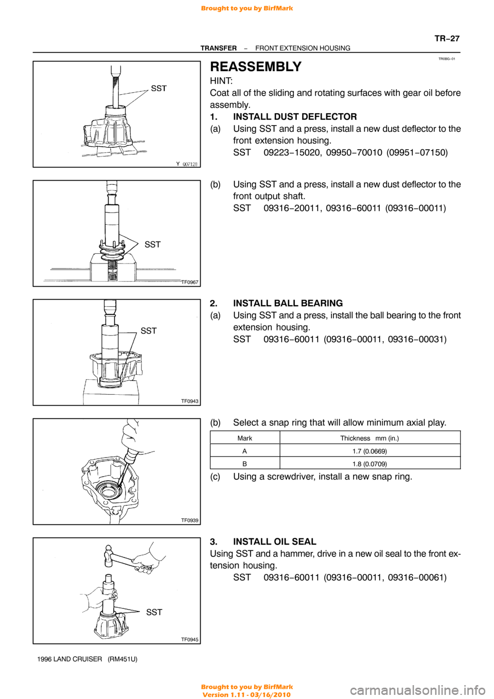
1. INSTALL DUST DEFLECTOR
(a) Using SST and a press, install a new dust deflector to the
front extension housing.
SST 09223−15020, 09950 −70010 (09951−07150)
(b) Using SST and a press, install a new dust deflector to the
front output shaft.
SST 09316−20011, 09316 −60011 (09316−00011)
2. INSTALL BALL BEARING
(a) Using SST and a press, install the ball bearing to the front
extension housing.
SST 09316−60011 (09316 −00011, 09316−00031)
(b) Select a snap ring that will allow minimum axial play.
MarkThickness mm (in.)
A1.7 (0.0669)
B1.8 (0.0709)
(c) Using a screwdriver, install a new snap ring.
3. INSTALL OIL SEAL
Using SST and a hammer, drive in a new oil seal to the front ex-
tension housing.
SST 09316−60011 (09316 −00011, 09316−00061)
Brought to you by BirfMark
Brought to you by BirfMark
Version 1.11 - 03/16/2010
Page 1390 of 1399
TR0BH−01
Q08383
Center Differential Control
Couping Assembly
Snap ring Vehicle Speed sensor
Drive Gear Ball Bearing
� Snap Ring
Snap Ring
Oil Pump Plate
Drive Rotor
Oil Pump Cover
Rear Extension housing
Oil Pump Drive Shaft Ball
Spring �
Screw Plug
Valve Seat
�
Dust Deflector
� Oil Seal Seal Ring
Rear Output Shaft
� Non− reusable Part
� Precoated part Separator
Driven Rotor
−
TRANSFER REAR EXTENSION HOUSING
TR−29
839
Author�: Date�:
1996 LAND CRUISER (RM451U)
REAR EXTENSION HOUSING
COMPONENTS
Brought to you by BirfMark
Brought to you by BirfMark
Version 1.11 - 03/16/2010
Page 1391 of 1399

TR0BI−01
Q00530
Q08384
Q02549
Q07138
TR−30
−
TRANSFER REAR EXTENSION HOUSING
1996 LAND CRUISER (RM451U)
DISASSEMBLY
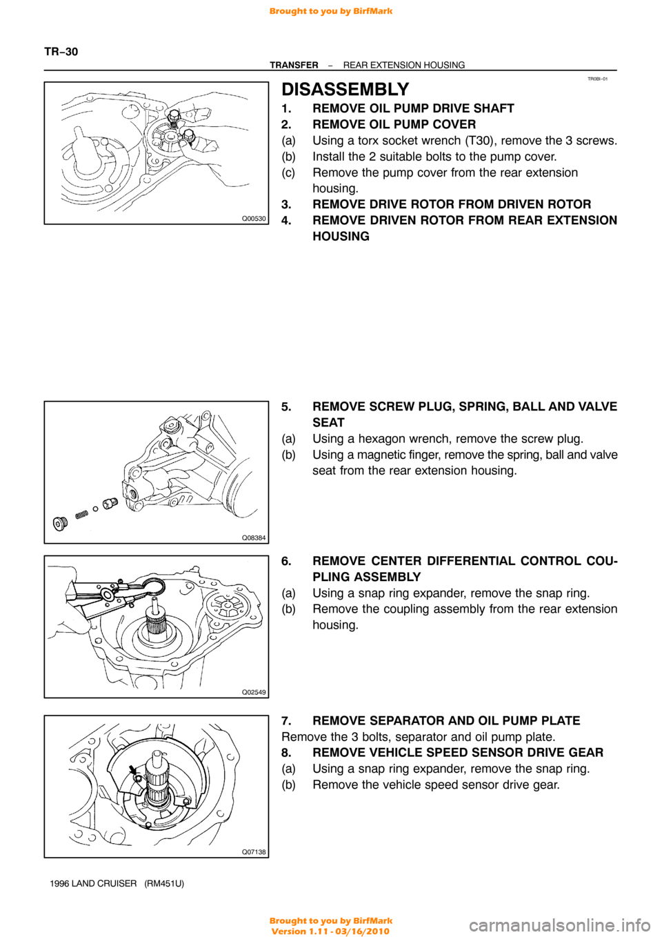
1. REMOVE OIL PUMP DRIVE SHAFT
2. REMOVE OIL PUMP COVER
(a) Using a torx socket wrench (T30), remove the 3 screws.
(b) Install the 2 suitable bolts to the pump cover.
(c) Remove the pump cover from the rear extension housing.
3. REMOVE DRIVE ROTOR FROM DRIVEN ROTOR
4. REMOVE DRIVEN ROTOR FROM REAR EXTENSION HOUSING
5. REMOVE SCREW PLUG, SPRING, BALL AND VALVE SEAT
(a) Using a hexagon wrench, remove the screw plug.
(b) Using a magnetic finger, remove the spring, ball and valve
seat from the rear extension housing.
6. REMOVE CENTER DIFFERENTIAL CONTROL COU- PLING ASSEMBLY
(a) Using a snap ring expander, remove the snap ring.
(b) Remove the coupling assembly from the rear extension housing.
7. REMOVE SEPARATOR AND OIL PUMP PLATE
Remove the 3 bolts, separator and oil pump plate.
8. REMOVE VEHICLE SPEED SENSOR DRIVE GEAR
(a) Using a snap ring expander, remove the snap ring.
(b) Remove the vehicle speed sensor drive gear.
Brought to you by BirfMark
Brought to you by BirfMark
Version 1.11 - 03/16/2010
Page 1392 of 1399
TF0959
SST
Q08385
Q08481
SST
−
TRANSFER REAR EXTENSION HOUSING
TR−31
1996 LAND CRUISER (RM451U)
9. REMOVE REAR OUTPUT SHAFT
(a) Using a snap ring expander, remove the snap ring.
(b) Using SST and a hammer, remove the rear output shaft.
SST 09325−12010
(c) Remove the 2 seal rings from the rear output shaft.
10. REMOVE DUST DEFLECTOR
(a) Using a screwdriver and hammer, remove the rear exten-
sion housing dust deflector.
(b) Using a screwdriver and hammer, remove the rear output
shaft dust deflector.
11. REMOVE OIL SEAL
Using a screwdriver, pry out the oil seal from the rear extension
housing.
12. REMOVE BALL BEARING
(a) Using a screwdriver, remove the snap ring.
(b) Using SST and a press, remove the ball bearing to the rear extension housing.
SST 09316−60011 (09316 −00011, 09316−00021)
Brought to you by BirfMark
Brought to you by BirfMark
Version 1.11 - 03/16/2010