Page 1090 of 1399
SA1UM−03
FA2038
−
SUSPENSION AND AXLE FRONT DIFFERENTIAL CARRIER
SA−27
1996 LAND CRUISER (RM451U)
REMOVAL
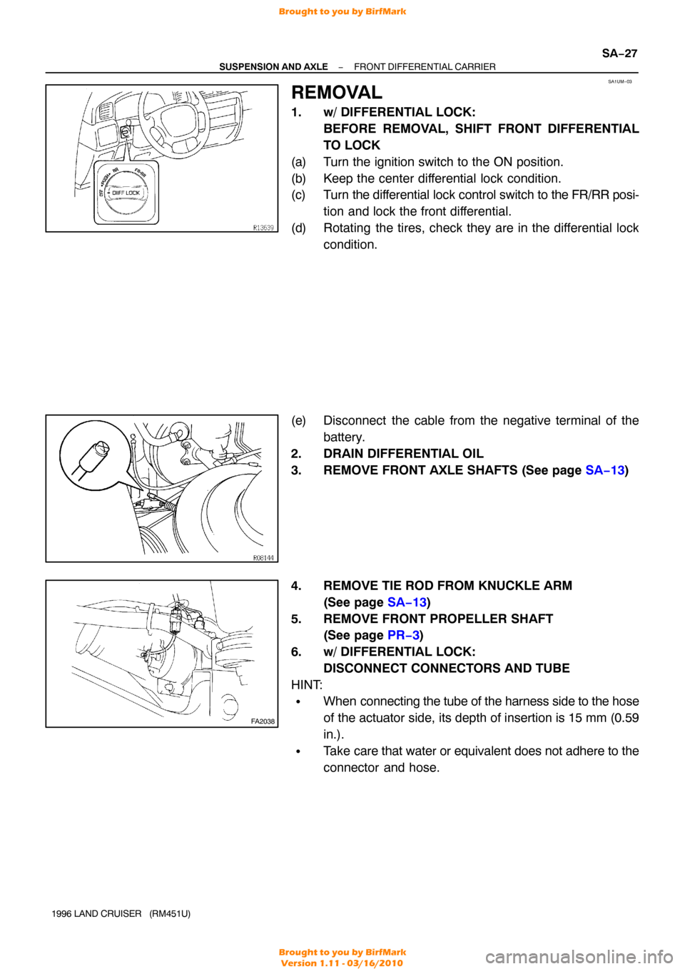
1. w/ DIFFERENTIAL LOCK:
BEFORE REMOVAL, SHIFT FRONT DIFFERENTIAL
TO LOCK
(a) Turn the ignition switch to the ON position.
(b) Keep the center differential lock condition.
(c) Turn the differential lock control switch to the FR/RR posi-
tion and lock the front differential.
(d) Rotating the tires, check they are in the differential lock condition.
(e) Disconnect the cable from the negative terminal of the battery.
2. DRAIN DIFFERENTIAL OIL
3. REMOVE FRONT AXLE SHAFTS (See page SA−13)
4. REMOVE TIE ROD FROM KNUCKLE ARM (See page SA−13 )
5. REMOVE FRONT PROPELLER SHAFT (See page PR−3 )
6. w/ DIFFERENTIAL LOCK: DISCONNECT CONNECTORS AND TUBE
HINT:
�When connecting the tube of the harness side to the hose
of the actuator side, its depth of insertion is 15 mm (0.59
in.).
�Take care that water or equivalent does not adhere to the
connector and hose.
Brought to you by BirfMark
Brought to you by BirfMark
Version 1.11 - 03/16/2010
Page 1099 of 1399
SA0510
SA1UP−03
Z06893
Z06894
R08149
SA−36
−
SUSPENSION AND AXLE FRONT DIFFERENTIAL CARRIER
1996 LAND CRUISER (RM451U)
REASSEMBLY
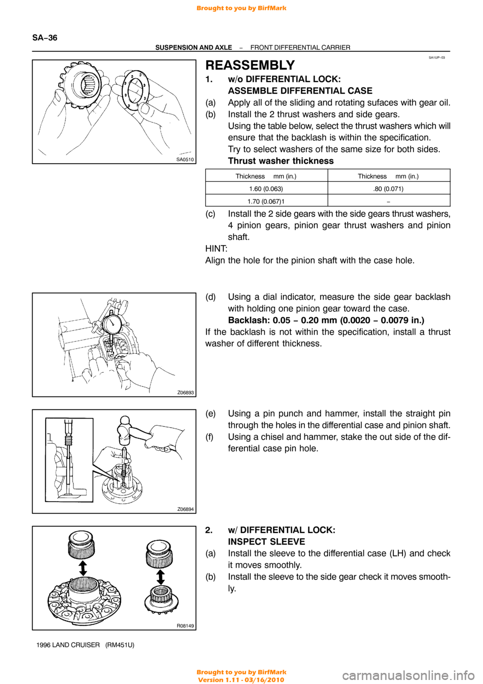
1. w/o DIFFERENTIAL LOCK: ASSEMBLE DIFFERENTIAL CASE
(a) Apply all of the sliding and rotating sufaces with gear oil.
(b) Install the 2 thrust washers and side gears. Using the table below, select the thrust washers which will
ensure that the backlash is within the specification.
Try to select washers of the same size for both sides.
Thrust washer thickness
Thickness mm (in.)Thickness mm (in.)
1.60 (0.063).80 (0.071)
1.70 (0.067)1−
(c) Install the 2 side gears with the side gears thrust washers,
4 pinion gears, pinion gear thrust washers and pinion
shaft.
HINT:
Align the hole for the pinion shaft with the case hole.
(d) Using a dial indicator, measure the side gear backlash with holding one pinion gear toward the case.
Backlash: 0.05 − 0.20 mm (0.0020 − 0.0079 in.)
If the backlash is not within the specification, install a thrust
washer of different thickness.
(e) Using a pin punch and hammer, install the straight pin through the holes in the dif ferential case and pinion shaft.
(f) Using a chisel and hammer, stake the out side of the dif- ferential case pin hole.
2. w/ DIFFERENTIAL LOCK: INSPECT SLEEVE
(a) Install the sleeve to the differential case (LH) and check
it moves smoothly.
(b) Install the sleeve to the side gear check it moves smooth-
ly.
Brought to you by BirfMark
Brought to you by BirfMark
Version 1.11 - 03/16/2010
Page 1102 of 1399
SA2465
SA2406
SST
SA2203
SSTSST
Front
Rear
FA2042
SST
R13140
SST
−
SUSPENSION AND AXLE FRONT DIFFERENTIAL CARRIER
SA−39
1996 LAND CRUISER (RM451U)
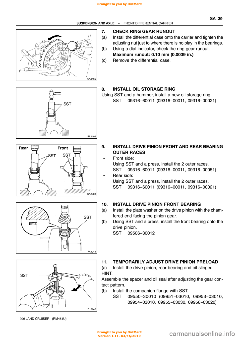
7. CHECK RING GEAR RUNOUT
(a) Install the differential case onto the carrier and tighten the
adjusting nut just to where there is no play in the bearings.
(b) Using a dial indicator, check the ring gear runout. Maximum runout: 0.10 mm (0.0039 in.)
(c) Remove the differential case.
8. INSTALL OIL STORAGE RING
Using SST and a hammer, install a new oil storage ring. SST 09316−60011 (09316 −00011, 09316−00021)
9. INSTALL DRIVE PINION FRONT AND REAR BEARING
OUTER RACES
�Front side:
Using SST and a press, install the 2 outer races.
SST 09316−60011 (09316 −00011, 09316−00051)
�Rear side:
Using SST and a press, install the 2 outer races.
SST 09316−60011 (09316 −00011, 09316−00021)
10. INSTALL DRIVE PINION FRONT BEARING
(a) Install the plate washer on the drive pinion with the cham-
fered end facing the pinion gear.
(b) Using SST and a press, install the front bearing onto the
drive pinion.
SST 09506−30012
11. TEMPORARILY ADJUST DRIVE PINION PRELOAD
(a) Install the drive pinion, rear bearing and oil slinger.
HINT:
Assemble the spacer and oil seal after adjusting the gear con-
tact pattern.
(b) Install the companion flange with SST. SST 09550 −30010 (09951 −03010, 09953 −03010,
09954 −03010, 09955 −03030, 09956−03020)
Brought to you by BirfMark
Brought to you by BirfMark
Version 1.11 - 03/16/2010
Page 1107 of 1399
SA2390
SST
SA2403
SA2471
SA−44
−
SUSPENSION AND AXLE FRONT DIFFERENTIAL CARRIER
1996 LAND CRUISER (RM451U)
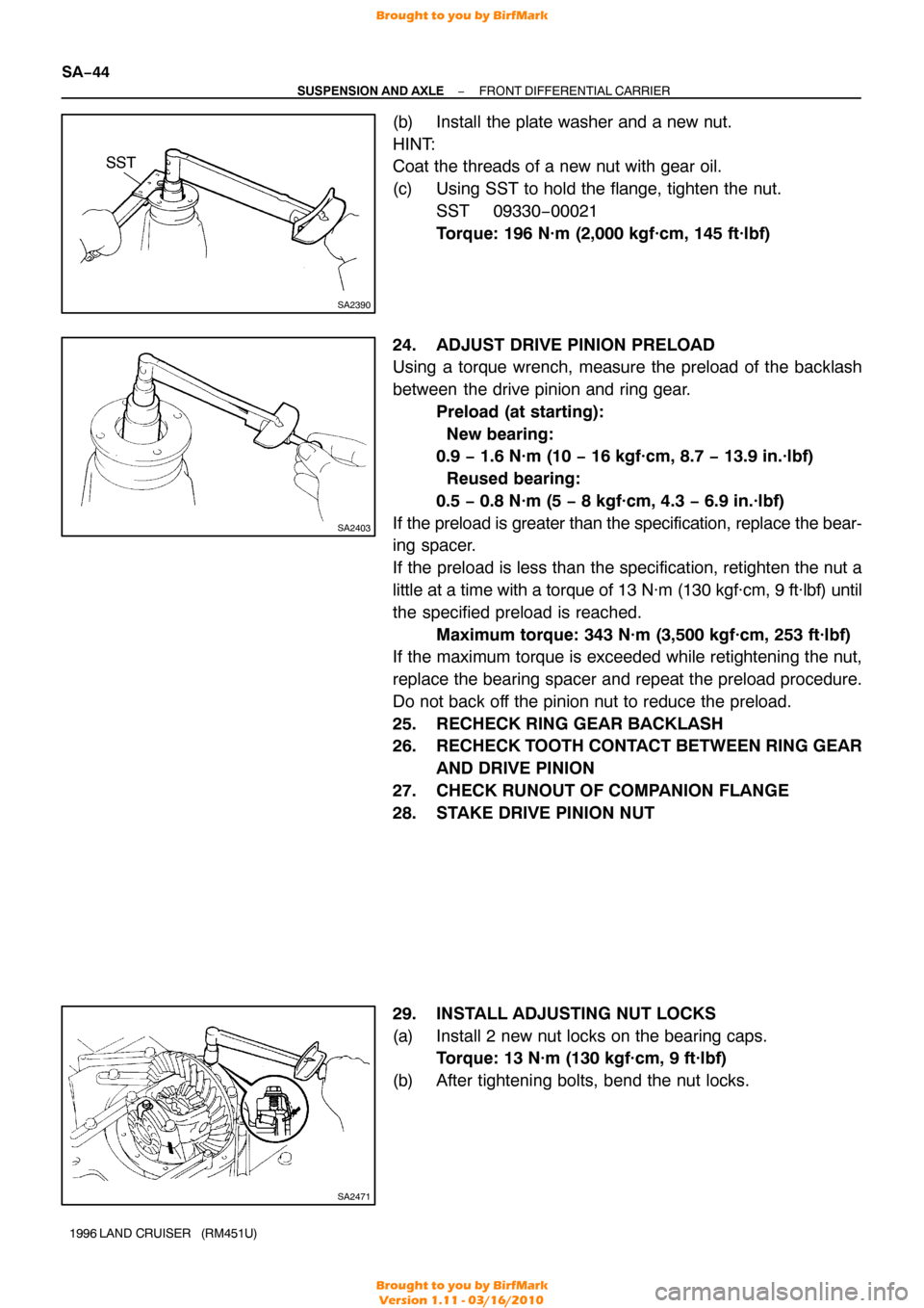
(b) Install the plate washer and a new nut.
HINT:
Coat the threads of a new nut with gear oil.
(c) Using SST to hold the flange, tighten the nut.
SST 09330−00021
Torque: 196 N·m (2,000 kgf·cm, 145 ft·lbf)
24. ADJUST DRIVE PINION PRELOAD
Using a torque wrench, measure the preload of the backlash
between the drive pinion and ring gear. Preload (at starting):
New bearing:
0.9 − 1.6 N·m (10 − 16 kgf·cm, 8.7 − 13.9 in.·lbf)
Reused bearing:
0.5 − 0.8 N·m (5 − 8 kgf·cm, 4.3 − 6.9 in.·lbf)
If the preload is greater than the specification, replace the bear-
ing spacer.
If the preload is less than the specification, retighten the nut a
little at a time with a torque of 13 N·m (130 kgf·cm, 9 ft·lbf) until
the specified preload is reached. Maximum torque: 343 N·m (3,500 kgf·cm, 253 ft·lbf)
If the maximum torque is exceeded while retightening the nut,
replace the bearing spacer and repeat the preload procedure.
Do not back off the pinion nut to reduce the preload.
25. RECHECK RING GEAR BACKLASH
26. RECHECK TOOTH CONTACT BETWEEN RING GEAR
AND DRIVE PINION
27. CHECK RUNOUT OF COMPANION FLANGE
28. STAKE DRIVE PINION NUT
29. INSTALL ADJUSTING NUT LOCKS
(a) Install 2 new nut locks on the bearing caps. Torque: 13 N·m (130 kgf·cm, 9 ft·lbf)
(b) After tightening bolts, bend the nut locks.
Brought to you by BirfMark
Brought to you by BirfMark
Version 1.11 - 03/16/2010
Page 1111 of 1399
SA1UQ−01
SA−48
−
SUSPENSION AND AXLE FRONT DIFFERENTIAL CARRIER
1996 LAND CRUISER (RM451U)
INSTALLATION
Installation is in the reverse order of removal (see page SA−27).
HINT:
�w/ differential lock:
Before installation, check differential lock operation connecting the connector of the actuator to the
connector of the vehicle side.
�w/ differential lock:
Before installation, check that the sleeves on work with switching over the differential lock control
switch.
After checking, lock the front differential.
�After installation, fill the differential with gear oil (See page SA−27).
�w/ differential lock:
After installation, check that the bleeder plug at the point of the bleeder tu\
be (inside of the engine room)
is not damaged or worn.
Brought to you by BirfMark
Brought to you by BirfMark
Version 1.11 - 03/16/2010
Page 1114 of 1399
SA1UT−01
FA0530
−
SUSPENSION AND AXLE COIL SPRING AND FRONT SHOCK ABSORBER
SA−51
1996 LAND CRUISER (RM451U)
INSPECTION
INSPECT SHOCK ABSORBER
Compress and extend the shock absorber rod and check that
there is abnormal resistance or unusual operation sounds.
If there is any abnormality, replace the shock absorber with a
new one.
NOTICE:
When discarding the shock absorber, use the following
procedure.
Brought to you by BirfMark
Brought to you by BirfMark
Version 1.11 - 03/16/2010
Page 1127 of 1399
SA1V6−01
RA0377
SA−64
−
SUSPENSION AND AXLE REAR AXLE SHAFT
1996 LAND CRUISER (RM451U)
INSPECTION
1. INSPECT REAR AXLE SHAFT
(a) Check for wear or damage.
(b) Using a dial indicator, check the runout of axle shaft. Maximum runout: 0.8 mm (0.031 in.)
If the runout is greater than the maximum, replace the axle
shaft.
2. REPLACE OIL SEAL
(a) Using SST, remove the oil seal. SST 09308−00010
(b) Using SST and a hammer, install a new oil seal into the hub.
SST 09517−36010
(c) Apply MP grease to the oil seal lip.
Brought to you by BirfMark
Brought to you by BirfMark
Version 1.11 - 03/16/2010
Page 1132 of 1399
SA1VB−01
R08001
Lock Nut Mark
Axle Housing
Mark
−
SUSPENSION AND AXLE REAR AXLE HUB
SA−69
1996 LAND CRUISER (RM451U)
INSTALLATION
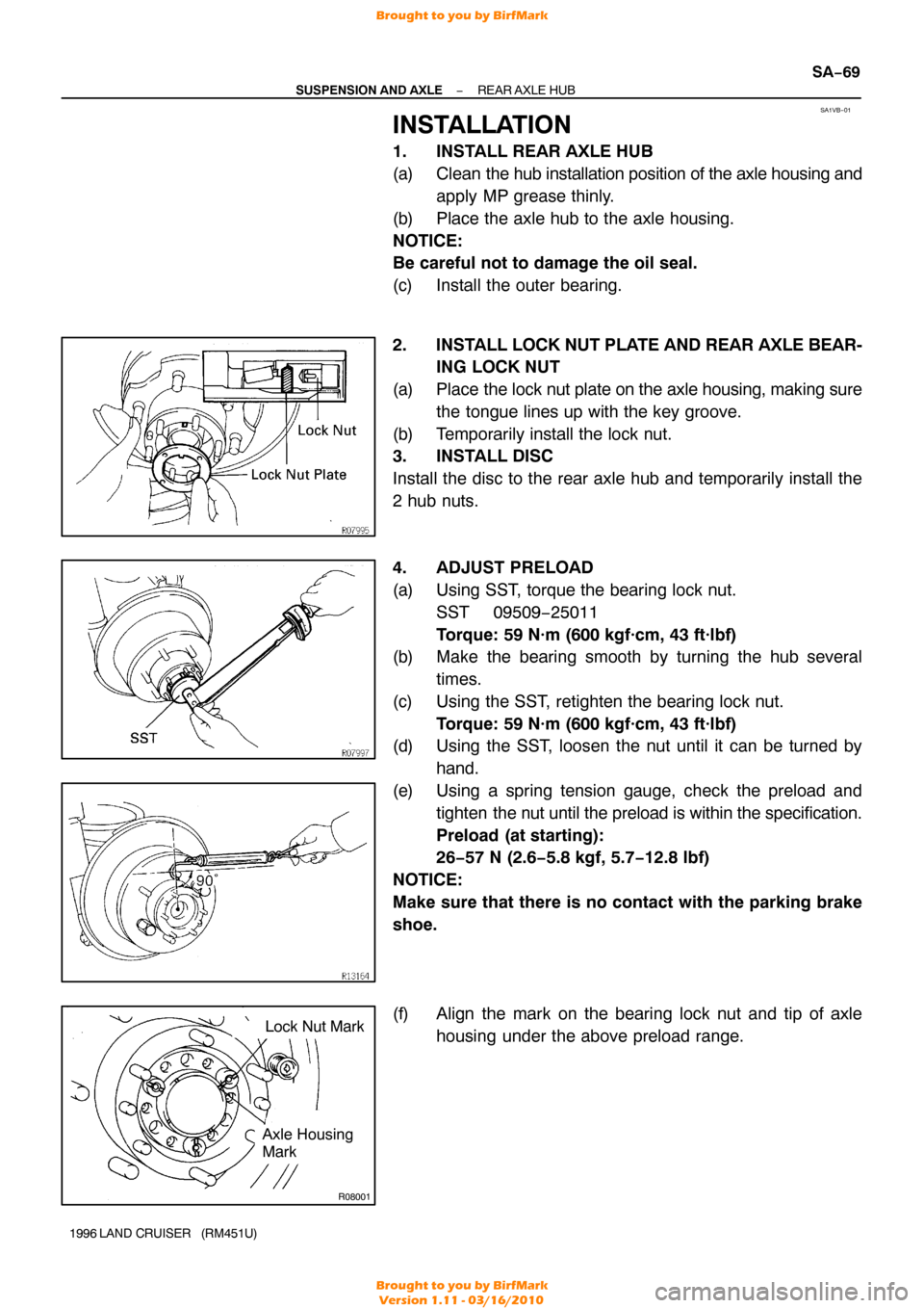
1. INSTALL REAR AXLE HUB
(a) Clean the hub installation position of the axle housing and
apply MP grease thinly.
(b) Place the axle hub to the axle housing.
NOTICE:
Be careful not to damage the oil seal.
(c) Install the outer bearing.
2. INSTALL LOCK NUT PLATE AND REAR AXLE BEAR- ING LOCK NUT
(a) Place the lock nut plate on the axle housing, making sure
the tongue lines up with the key groove.
(b) Temporarily install the lock nut.
3. INSTALL DISC
Install the disc to the rear axle hub and temporarily install the
2 hub nuts.
4. ADJUST PRELOAD
(a) Using SST, torque the bearing lock nut.SST 09509−25011
Torque: 59 N·m (600 kgf·cm, 43 ft·lbf)
(b) Make the bearing smooth by turning the hub several
times.
(c) Using the SST, retighten the bearing lock nut. Torque: 59 N·m (600 kgf·cm, 43 ft·lbf)
(d) Using the SST, loosen the nut until it can be turned by
hand.
(e) Using a spring tension gauge, check the preload and tighten the nut until the preload is within the specification.
Preload (at starting):
26−57 N (2.6−5.8 kgf, 5.7−12.8 lbf)
NOTICE:
Make sure that there is no contact with the parking brake
shoe.
(f) Align the mark on the bearing lock nut and tip of axle housing under the above preload range.
Brought to you by BirfMark
Brought to you by BirfMark
Version 1.11 - 03/16/2010