Page 1257 of 1399
SR166−01
R07281
Normal Abnormal
SR−4
−
STEERING POWER STEERING FLUID
1996 LAND CRUISER (RM451U)
INSPECTION
1. CHECK FLUID LEVEL
(a) Keep the vehicle level.
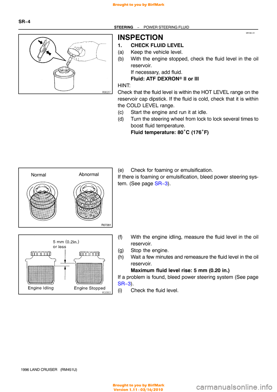
(b) With the engine stopped, check the fluid level in the oil reservoir.
If necessary, add fluid.
Fluid: ATF DEXRON® II or III
HINT:
Check that the fluid level is within the HOT LEVEL range on the
reservoir cap dipstick. If the fluid is cold, check that it is within
the COLD LEVEL range.
(c) Start the engine and run it at idle.
(d) Turn the steering wheel from lock to lock several times to
boost fluid temperature.
Fluid temperature: 80° C (176°F)
(e) Check for foaming or emulsification.
If there is foaming or emulsification, bleed power steering sys-
tem. (See page SR−3 ).
(f) With the engine idling, measure the fluid level in the oil reservoir.
(g) Stop the engine.
(h) Wait a few minutes and remeasure the fluid level in the oil reservoir.
Maximum fluid level rise: 5 mm (0.20 in.)
If a problem is found, bleed power steering system (See page
SR−3 ).
(i) Check the fluid level.
Brought to you by BirfMark
Brought to you by BirfMark
Version 1.11 - 03/16/2010
Page 1258 of 1399
Z15498
PS GearClosed
SST PS Vane
Pump
Oil
Reservoir
−
STEERING POWER STEERING FLUID
SR−5
1996 LAND CRUISER (RM451U)
2. CHECK STEERING FLUID PRESSURE
(a) Disconnect the pressure feed tube from the PS vane
pump (See page SR−23).
(b) Connect SST over 2 new gaskets, as shown below. SST 09640 −10010 (09641 −01010, 09641 −01030,
09641 −01060)
NOTICE:
Check that the valve of the SST is in the open position.
(c) Bleed the power steering system (See page SR−3).
(d) Start the engine and run it at idle.
(e) Turn the steering wheel from lock to lock several times to
boost fluid temperature.
Fluid temperature: 80° C (176°F)
(f) With the engine idling, close the valve of the SST and ob-
serve the reading on the SST.
Minimum fluid pressure:
9,316kPa (95 kgf/cm
2, 1,351 psi)
NOTICE:
�Do not keep the valve closed for more than 10 se-
conds.
�Do not let the fluid temperature become too high.
Brought to you by BirfMark
Brought to you by BirfMark
Version 1.11 - 03/16/2010
Page 1278 of 1399
SR16I−02
R15644
Vane Pump ShaftFront
Housing Bushing
Micrometer
Caliper
Gauge
N00372
Height Thickness
Length
R10282
Feeler Gauge
R15645Inscribed Mark
−
STEERING POWER STEERING VANE PUMP
SR−27
1996 LAND CRUISER (RM451U)
INSPECTION
1. CHECK OIL CLEARANCE BETWEEN VANE PUMP
SHAFT AND BUSHING
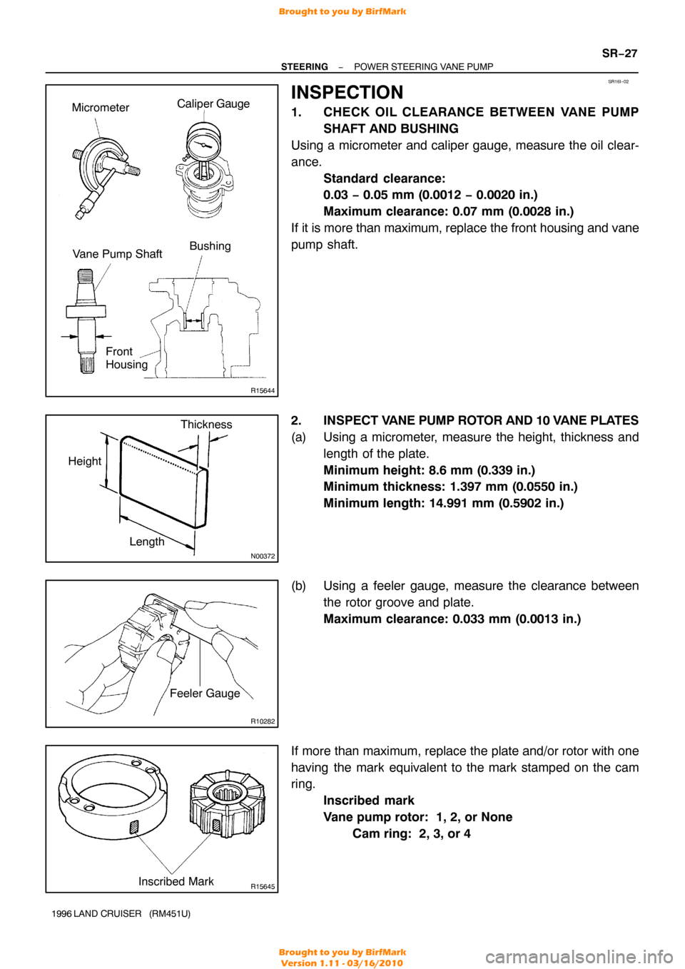
Using a micrometer and caliper gauge, measure the oil clear-
ance. Standard clearance:
0.03 − 0.05 mm (0.0012 − 0.0020 in.)
Maximum clearance: 0.07 mm (0.0028 in.)
If it is more than maximum, replace the front housing and vane
pump shaft.
2. INSPECT V ANE PUMP ROTOR AND 10 VANE PLATES
(a) Using a micrometer, measure the height, thickness and length of the plate.
Minimum height: 8.6 mm (0.339 in.)
Minimum thickness: 1.397 mm (0.0550 in.)
Minimum length: 14.991 mm (0.5902 in.)
(b) Using a feeler gauge, measure the clearance between the rotor groove and plate.
Maximum clearance: 0.033 mm (0.0013 in.)
If more than maximum, replace the plate and/or rotor with one
having the mark equivalent to the mark stamped on the cam
ring. Inscribed mark
Vane pump rotor: 1, 2, or None
Cam ring: 2, 3, or 4
Brought to you by BirfMark
Brought to you by BirfMark
Version 1.11 - 03/16/2010
Page 1291 of 1399
SR16O−01
Z14503
Dial Indicator30 mm
(1.18 in.)
Z14504
Dial Indicator
Z10600
Z06211
SR−38
−
STEERING POWER STEERING GEAR
1996 LAND CRUISER (RM451U)
INSPECTION
NOTICE:
When using a vise, do not overtighten it.
1. INSPECT BALL CLEARANCE
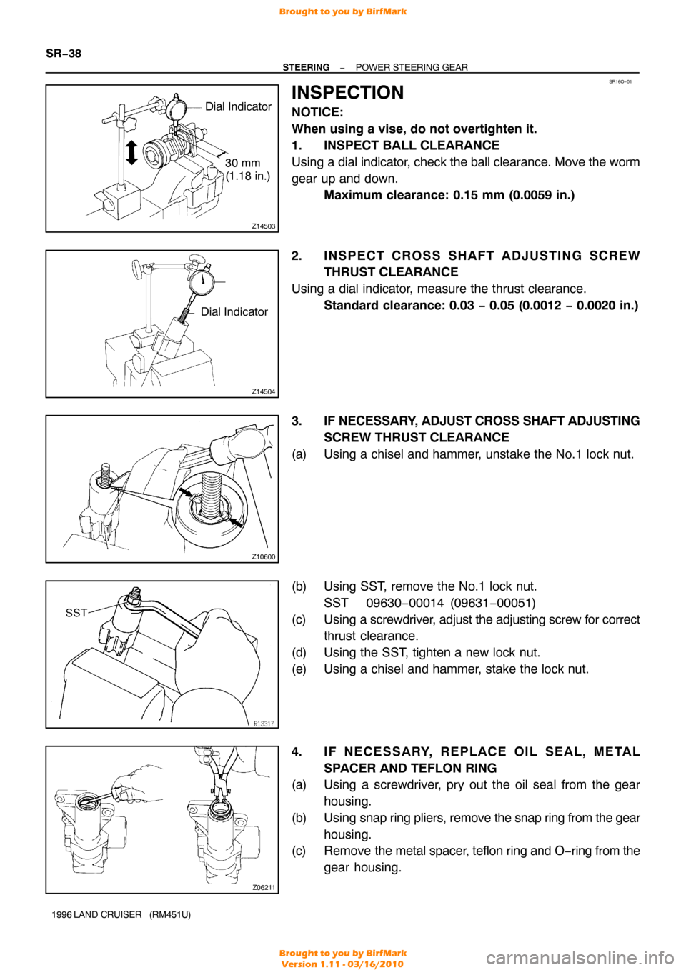
Using a dial indicator, check the ball clearance. Move the worm
gear up and down. Maximum clearance: 0.15 mm (0.0059 in.)
2. INSPECT CROSS SHAFT ADJUSTING SCREW THRUST CLEARANCE
Using a dial indicator, measure the thrust clearance. Standard clearance: 0.03 − 0.05 (0.0012 − 0.0020 in.)
3. IF NECESSARY, ADJUST CROSS SHAFT ADJUSTING SCREW THRUST CLEARANCE
(a) Using a chisel and hammer, unstake the No.1 lock nut.
(b) Using SST, remove the No.1 lock nut. SST 09630−00014 (09631 −00051)
(c) Using a screwdriver, adjust the adjusting screw for correct thrust clearance.
(d) Using the SST, tighten a new lock nut.
(e) Using a chisel and hammer, stake the lock nut.
4. IF NECESSARY, REPLACE OIL SEAL, METAL SPACER AND TEFLON RING
(a) Using a screwdriver, pry out the oil seal from the gear
housing.
(b) Using snap ring pliers, remove the snap ring from the gear
housing.
(c) Remove the metal spacer, teflon ring and O −ring from the
gear housing.
Brought to you by BirfMark
Brought to you by BirfMark
Version 1.11 - 03/16/2010
Page 1309 of 1399
SS−8
−
SERVICE SPECIFICATIONS ENGINE MECHANICAL
1996 LAND CRUISER (RM451U)
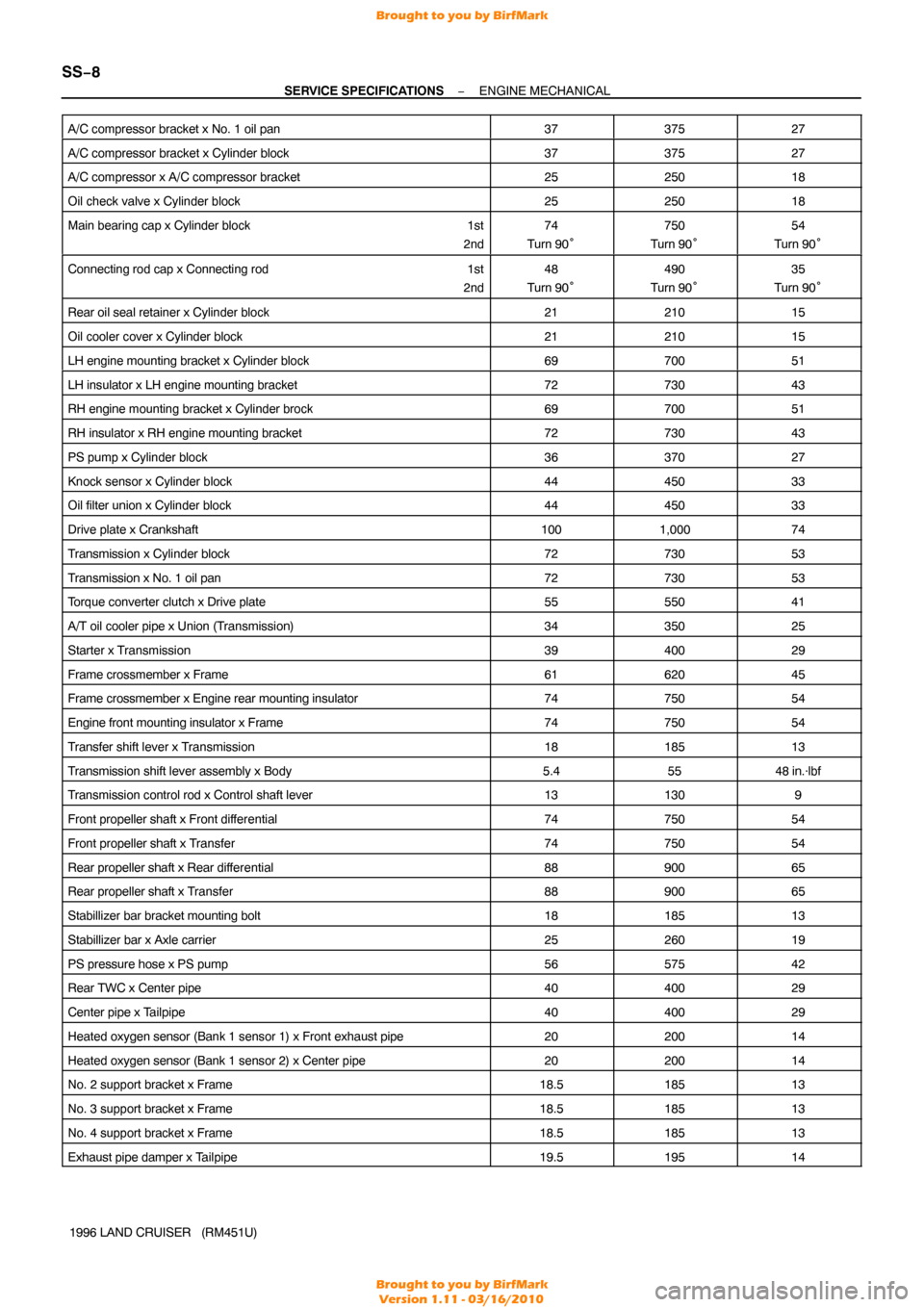
A/C compressor bracket x No. 1 oil pan
3737527
A/C compressor bracket x Cylinder block3737527
A/C compressor x A/C compressor bracket2525018
Oil check valve x Cylinder block2525018
Main bearing cap x Cylinder block
1st
2nd74
Turn 90°750
Turn 90°54
Turn 90°
Connecting rod cap x Connecting rod 1st
2nd48
Turn 90°490
Turn 90°35
Turn 90°
Rear oil seal retainer x Cylinder block2121015
Oil cooler cover x Cylinder block2121015
LH engine mounting bracket x Cylinder block6970051
LH insulator x LH engine mounting bracket7273043
RH engine mounting bracket x Cylinder brock6970051
RH insulator x RH engine mounting bracket7273043
PS pump x Cylinder block3637027
Knock sensor x Cylinder block4445033
Oil filter union x Cylinder block4445033
Drive plate x Crankshaft1001,00074
Transmission x Cylinder block7273053
Transmission x No. 1 oil pan7273053
Torque converter clutch x Drive plate5555041
A/T oil cooler pipe x Union (Transmission)3435025
Starter x Transmission3940029
Frame crossmember x Frame6162045
Frame crossmember x Engine rear mounting insulator7475054
Engine front mounting insulator x Frame7475054
Transfer shift lever x Transmission1818513
Transmission shift lever assembly x Body5.45548 in.·lbf
Transmission control rod x Control shaft lever131309
Front propeller shaft x Front dif ferential7475054
Front propeller shaft x Transfer7475054
Rear propeller shaft x Rear differential8890065
Rear propeller shaft x Transfer8890065
Stabillizer bar bracket mounting bolt1818513
Stabillizer bar x Axle carrier2526019
PS pressure hose x PS pump5657542
Rear TWC x Center pipe4040029
Center pipe x Tailpipe4040029
Heated oxygen sensor (Bank 1 sensor 1) x Front exhaust pipe2020014
Heated oxygen sensor (Bank 1 sensor 2) x Center pipe2020014
No. 2 support bracket x Frame18.518513
No. 3 support bracket x Frame18.518513
No. 4 support bracket x Frame18.518513
Exhaust pipe damper x Tailpipe19.519514
Brought to you by BirfMark
Brought to you by BirfMark
Version 1.11 - 03/16/2010
Page 1317 of 1399
SS1EX−04
SS−16
−
SERVICE SPECIFICATIONS LUBRICATION
1996 LAND CRUISER (RM451U)
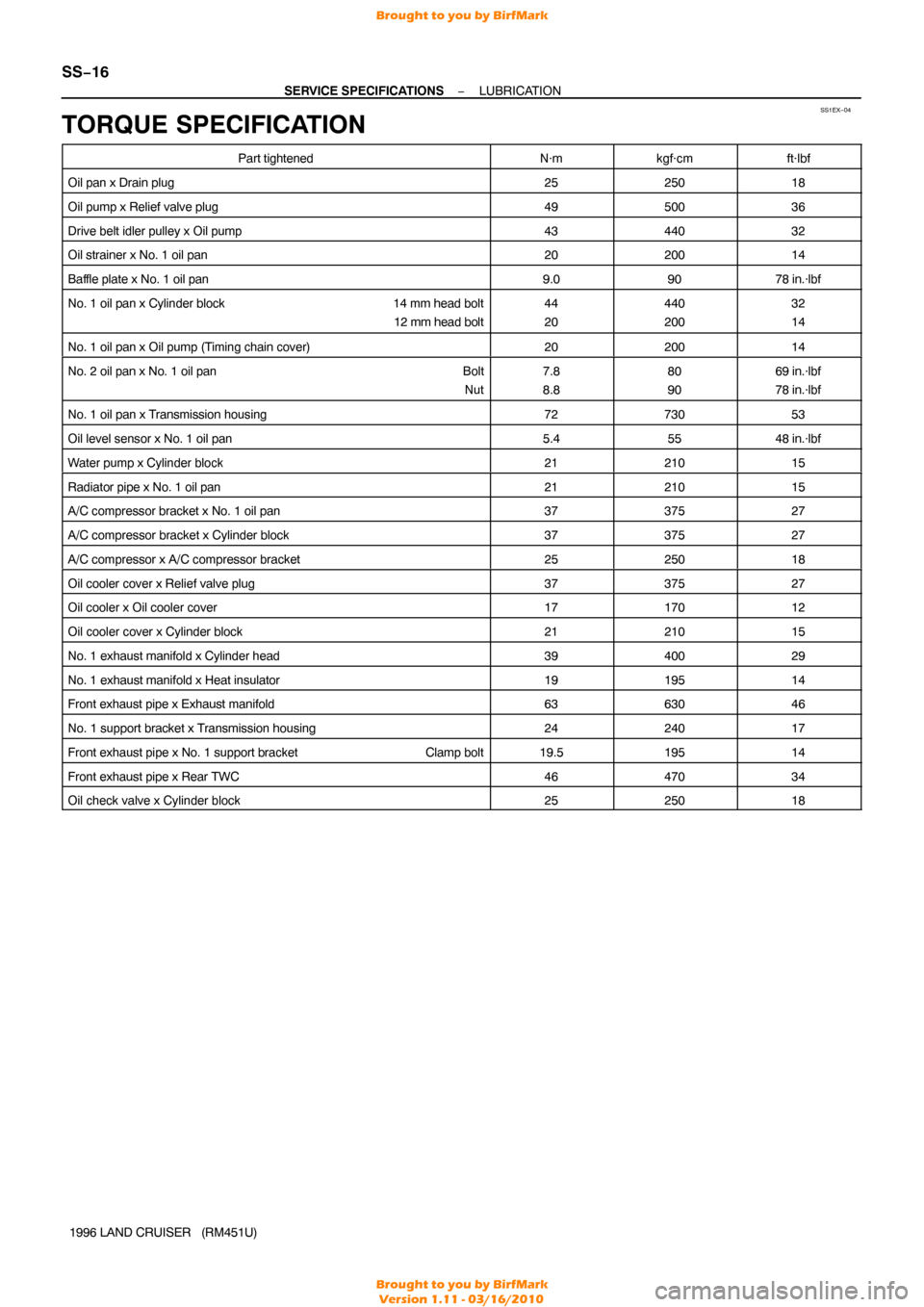
TORQUE SPECIFICATION
Part tightenedN·mkgf·cmft·lbf
Oil pan x Drain plug2525018
Oil pump x Relief valve plug4950036
Drive belt idler pulley x Oil pump4344032
Oil strainer x No. 1 oil pan2020014
Baffle plate x No. 1 oil pan9.09078 in.·lbf
No. 1 oil pan x Cylinder block 14 mm head bolt
12 mm head bolt44
20440
20032
14
No. 1 oil pan x Oil pump (Timing chain cover)2020014
No. 2 oil pan x No. 1 oil pan Bolt
Nut7.8
8.880
9069 in.·lbf
78 in.·lbf
No. 1 oil pan x Transmission housing7273053
Oil level sensor x No. 1 oil pan5.45548 in.·lbf
Water pump x Cylinder block2121015
Radiator pipe x No. 1 oil pan2121015
A/C compressor bracket x No. 1 oil pan3737527
A/C compressor bracket x Cylinder block3737527
A/C compressor x A/C compressor bracket2525018
Oil cooler cover x Relief valve plug3737527
Oil cooler x Oil cooler cover1717012
Oil cooler cover x Cylinder block2121015
No. 1 exhaust manifold x Cylinder head3940029
No. 1 exhaust manifold x Heat insulator1919514
Front exhaust pipe x Exhaust manifold6363046
No. 1 support bracket x Transmission housing2424017
Front exhaust pipe x No. 1 support bracket Clamp bolt19.519514
Front exhaust pipe x Rear TWC4647034
Oil check valve x Cylinder block2525018
Brought to you by BirfMark
Brought to you by BirfMark
Version 1.11 - 03/16/2010
Page 1352 of 1399
P10584
OhmmeterContinuity
ST0N8−01
P10585
Ohmmeter
No Continuity
P10586
P10587
ST0040
−
STARTING STARTER
ST−7
1996 LAND CRUISER (RM451U)
INSPECTION
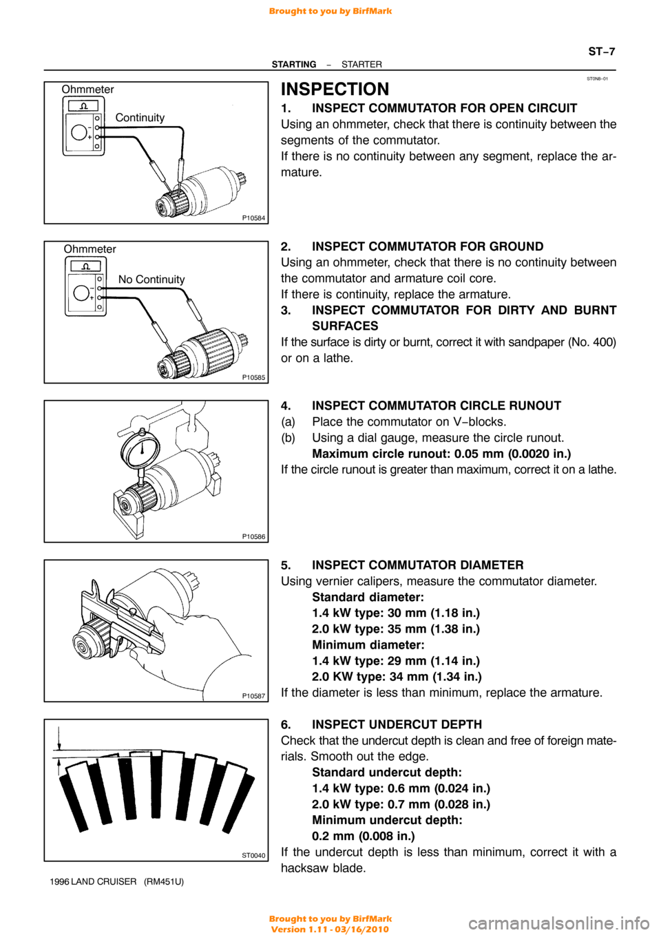
1. INSPECT COMMUTATOR FOR OPEN CIRCUIT
Using an ohmmeter, check that there is continuity between the
segments of the commutator.
If there is no continuity between any segment, replace the ar-
mature.
2. INSPECT COMMUTATOR FOR GROUND
Using an ohmmeter, check that there is no continuity between
the commutator and armature coil core.
If there is continuity, replace the armature.
3. INSPECT COMMUTATOR FOR DIRTY AND BURNT
SURFACES
If the surface is dirty or burnt, correct it with sandpaper (No. 400)
or on a lathe.
4. INSPECT COMMUTATOR CIRCLE RUNOUT
(a) Place the commutator on V−blocks.
(b) Using a dial gauge, measure the circle runout. Maximum circle runout: 0.05 mm (0.0020 in.)
If the circle runout is greater than maximum, correct it on a lathe.
5. INSPECT COMMUTATOR DIAMETER
Using vernier calipers, measure the commutator diameter. Standard diameter:
1.4 kW type: 30 mm (1.18 in.)
2.0 kW type: 35 mm (1.38 in.)
Minimum diameter:
1.4 kW type: 29 mm (1.14 in.)
2.0 KW type: 34 mm (1.34 in.)
If the diameter is less than minimum, replace the armature.
6. INSPECT UNDERCUT DEPTH
Check that the undercut depth is clean and free of foreign mate-
rials. Smooth out the edge.
Standard undercut depth:
1.4 kW type: 0.6 mm (0.024 in.)
2.0 kW type: 0.7 mm (0.028 in.)
Minimum undercut depth:
0.2 mm (0.008 in.)
If the undercut depth is less than minimum, correct it with a
hacksaw blade.
Brought to you by BirfMark
Brought to you by BirfMark
Version 1.11 - 03/16/2010
Page 1353 of 1399
P10588
OhmmeterContinuity
P10589
Ohmmeter
No Continuity
Z14910
Brush Holder Side
Field Frame Side Length
Length
ST0019
ST−8
−
STARTING STARTER
1996 LAND CRUISER (RM451U)
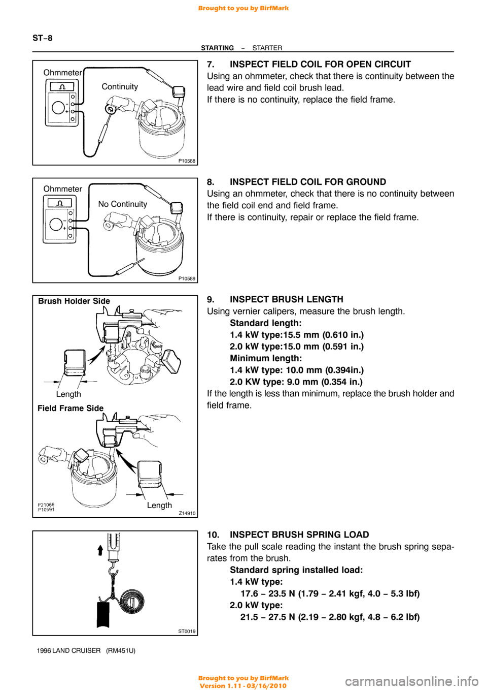
7. INSPECT FIELD COIL FOR OPEN CIRCUIT
Using an ohmmeter, check that there is continuity between the
lead wire and field coil brush lead.
If there is no continuity, replace the field frame.
8. INSPECT FIELD COIL FOR GROUND
Using an ohmmeter, check that there is no continuity between
the field coil end and field frame.
If there is continuity, repair or replace the field frame.
9. INSPECT BRUSH LENGTH
Using vernier calipers, measure the brush length.
Standard length:
1.4 kW type:15.5 mm (0.610 in.)
2.0 kW type:15.0 mm (0.591 in.)
Minimum length:
1.4 kW type: 10.0 mm (0.394in.)
2.0 KW type: 9.0 mm (0.354 in.)
If the length is less than minimum, replace the brush holder and
field frame.
10. INSPECT BRUSH SPRING LOAD
Take the pull scale reading the instant the brush spring sepa-
rates from the brush.
Standard spring installed load:
1.4 kW type:
17.6 − 23.5 N (1.79 − 2.41 kgf, 4.0 − 5.3 lbf)
2.0 kW type:
21.5 − 27.5 N (2.19 − 2.80 kgf, 4.8 − 6.2 lbf)
Brought to you by BirfMark
Brought to you by BirfMark
Version 1.11 - 03/16/2010