Page 2496 of 2890
. If
spacers cannot correct the gap, replace worn sensor or
worn tone wheel.
: Is an oscilloscope availab")
G4M0701
: Go to next.
: Adjust the gap.
NOTE:
Adjust the gap using spacer (Part No. 26755AA000). If
spacers cannot correct the gap, replace worn sensor or
worn tone wheel.
: Is an oscilloscope available?
: Go to next step.
: Go to step 10).
2) Raise all four wheels of ground.
3) Turn ignition switch OFF.
4) Disconnect connector from ABS control module.
5) Disconnect connector cover from connector.
6) Connect connector to ABS control module.
7) Connect the oscilloscope to the ABS control module
connector.
8) Turn ignition switch ON.
B4M0816A
9) Rotate wheels and measure voltage at specified fre-
quency.
NOTE:
When this inspection is completed, the ABS control mod-
ule sometimes stores the trouble code 29.
TROUBLE CODE / Connector & terminal:
(F49) No. 14 (+)—No. 15 (�) (Front RH)
(F49) No. 49 (+)—No. 19 (�) (Front LH)
(F49) No. 18 (+)—No. 46 (�) (Rear RH)
(F49) No. 16 (+)—No. 17 (�) (Rear LH)
Specified voltage: 0.12—1 V (When it is 20 Hz.)
: Is oscilloscope pattern smooth, as shown in
figure?
: Go to step10M4.
: Go to next step.
10) Remove disc rotor from hub.
: Is the ABS sensor pole piece or the tone
wheel contaminated by dirt or other foreign
matter?
: Thoroughly remove dirt or other foreign matter.
: Go to next.
156
4-4cBRAKES [ABS 5.3 TYPE]
10. Diagnostics Chart with Select Monitor
Page 2497 of 2890
: Are there broken or damaged teeth in the
ABS sensor pole piece or the tone wheel?
: Replace ABS sensor or tone wheel.
: Go to next step.
11) Measure hub runout.
: Is the runout less than 0.05 mm (0.0020 in)?
: Go to step10M4.
: Repair hub.
10M4
CHECK ABSCM.
1) Turn ignition switch to OFF.
2) Connect all connectors.
3) Erase the memory.
4) Perform inspection mode.
5) Read out the trouble code.
: Is the same trouble code as in the current
diagnosis still being output?
: Replace ABSCM.
: Go to next.
: Are other trouble codes being output?
: Proceed with the diagnosis corresponding to the
trouble code.
: A temporary poor contact.
157
4-4cBRAKES [ABS 5.3 TYPE]
10. Diagnostics Chart with Select Monitor
Page 2523 of 2890
B4M0838A
10V1
CHECK GROUND CIRCUIT OF ABSCM.
1) Turn ignition switch to OFF.
2) Disconnect connector from ABSCM.
3) Measure resistance between ABSCM and chassis
ground.
: Connector & terminal
(F49) No. 1—Chassis ground
(F49) No. 55—Chassis ground
Is resistance less than 0.5Ω?
: Go to step10V2.
: Repair ABSCM ground harness.
10V2CHECK POOR CONTACT IN CONNEC-
TORS BETWEEN BATTERY, IGNITION
SWITCH AND ABSCM.
: Is there poor contact in connectors between
battery, ignition switch and ABSCM?
: Repair connector.
: Go to step10V3.
10V3
CHECK SOURCES OF SIGNAL NOISE.
: Is the car telephone or the wireless trans-
mitter properly installed?
: Go to next.
: Properly install the car telephone or the wireless
transmitter.
: Are noise sources (such as an antenna)
installed near the sensor harness?
: Install the noise sources apart from the sensor
harness.
: Go to step10V4.
183
4-4cBRAKES [ABS 5.3 TYPE]
10. Diagnostics Chart with Select Monitor
Page 2537 of 2890
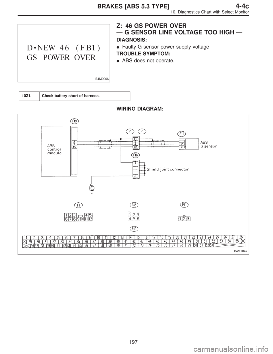
B4M0966
Z: 46 GS POWER OVER
—G SENSOR LINE VOLTAGE TOO HIGH—
DIAGNOSIS:
�Faulty G sensor power supply voltage
TROUBLE SYMPTOM:
�ABS does not operate.
10Z1.Check battery short of harness.
WIRING DIAGRAM:
B4M1047
197
4-4cBRAKES [ABS 5.3 TYPE]
10. Diagnostics Chart with Select Monitor
Page 2538 of 2890
B4M0855A
10Z1
CHECK BATTERY SHORT OF HARNESS.
1) Turn ignition switch to OFF.
2) Remove console cover from console box.
3) Disconnect connector from G sensor.
4) Disconnect connector from ABSCM.
5) Turn ignition switch to ON.
6) Measure voltage between ABSCM connector and chas-
sis ground.
: Connector & terminal
(F49) No. 8 (+)—Chassis ground (�)
(F49) No. 45 (+)—Chassis ground (�)
Is voltage 0 V?
: Go to next step.
: Repair harness between ABSCM and G sensor.
7) Turn ignition switch to OFF.
8) Measure voltage between ABSCM and chassis ground.
: Connector & terminal
(F49) No. 8 (+)—Chassis ground (�)
(F49) No. 45 (+)—Chassis ground (�)
Is voltage 0 V?
: Replace ABSCM.
: Repair harness between ABSCM and chassis
ground.
198
4-4cBRAKES [ABS 5.3 TYPE]
10. Diagnostics Chart with Select Monitor
Page 2539 of 2890
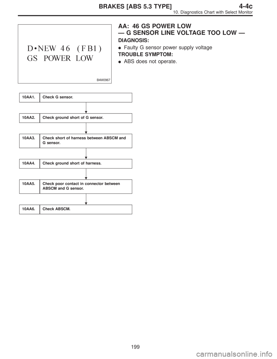
B4M0967
AA: 46 GS POWER LOW
—G SENSOR LINE VOLTAGE TOO LOW—
DIAGNOSIS:
�Faulty G sensor power supply voltage
TROUBLE SYMPTOM:
�ABS does not operate.
10AA1.Check G sensor.
10AA2.Check ground short of G sensor.
10AA3.Check short of harness between ABSCM and
G sensor.
10AA4.Check ground short of harness.
10AA5.Check poor contact in connector between
ABSCM and G sensor.
10AA6.Check ABSCM.
�
�
�
�
�
199
4-4cBRAKES [ABS 5.3 TYPE]
10. Diagnostics Chart with Select Monitor
Page 2540 of 2890
WIRING DIAGRAM:
B4M1047
B4M0851B
10AA1
CHECK G SENSOR.
1) Turn ignition switch to OFF.
2) Remove console cover from console box.
3) Disconnect connector from G sensor.
4) Measure resistance of G sensor.
: Connector & terminal
To (P11) No. 1—No. 3
Is resistance 50±8 kΩ?
: Go to step10AA2.
: Replace G sensor.
200
4-4cBRAKES [ABS 5.3 TYPE]
10. Diagnostics Chart with Select Monitor
Page 2541 of 2890
 No. 3—Bracket
Is resistance more than 1 MΩ?
: Go to step10AA3.
: Rep")
B4M0852B
10AA2
CHECK GROUND SHORT OF G SENSOR.
Measure resistance between G sensor and bracket.
: Connector & terminal
To (P11) No. 3—Bracket
Is resistance more than 1 MΩ?
: Go to step10AA3.
: Replace G sensor.
B4M0853A
10AA3CHECK SHORT OF HARNESS BETWEEN
ABSCM AND G SENSOR.
1) Disconnect connector from ABSCM.
2) Measure resistance between ABSCM connector termi-
nals.
: Connector & terminal
(F49) No. 45—No. 8
Is resistance more than 1 MΩ?
: Go to step10AA4.
: Repair harness between ABSCM and G sensor.
B4M0854A
10AA4
CHECK GROUND SHORT OF HARNESS.
Measure resistance between ABSCM connector and chas-
sis ground.
: Connector & terminal
(F49) No. 8—Chassis ground
(F49) No. 45—Chassis ground
Is resistance more than 1 MΩ?
: Go to step10AA5.
: Repair harness between ABSCM and G sensor.
10AA5CHECK POOR CONTACT IN CONNEC-
TOR BETWEEN ABSCM AND G SENSOR.
: Is there poor contact in connectors between
ABSCM and G sensor?
: Repair connector.
: Go to step10AA6.
201
4-4cBRAKES [ABS 5.3 TYPE]
10. Diagnostics Chart with Select Monitor
 Measure hub runout.
: Is the runout less than 0.05 mm (0.")
 Turn ignition switch to OFF.
2) Disconnect connector from ABSCM.
3) Measure resistance between ABSCM and chassis
ground.
: Connector & terminal
(F49) No")
 Turn ignition switch to OFF.
2) Remove console cover from console box.
3) Disconnect connector from G sensor.
4) Disconnect connector from ABSCM.
5) Tu")
 Turn ignition switch to OFF.
2) Remove console cover from console box.
3) Disconnect connector from G sensor.
4) Measure resistance of G senso")