Page 2485 of 2890

B4M0922
10L1CHECK OUTPUT OF ABS SENSOR
USING SELECT MONITOR.
Read the ABS sensor output corresponding to the faulty
system in the select monitor function mode.
NOTE:
The select monitor display shows that the front right wheel
is rotating at 30 km/h.
: Does the speed indicated on the display
change in response to the speedometer
reading during acceleration/deceleration
when the steering wheel is in the straight-
ahead position?
: Go to step10L2.
: Go to step10L3.
10L2CHECK POOR CONTACT IN CONNEC-
TOR BETWEEN ABSCM AND ABS SEN-
SOR.
: Is there poor contact in connectors between
ABSCM and ABS sensor?
: Repair connector.
: Go to step10L3.
10L3
CHECK SOURCES OF SIGNAL NOISE.
: Is the car telephone or the wireless trans-
mitter properly installed?
: Go to next.
: Properly install the car telephone or the wireless
transmitter.
: Are noise sources (such as an antenna)
installed near the sensor harness?
: Install the noise sources apart from the sensor
harness.
: Go to step10L4.
145
4-4cBRAKES [ABS 5.3 TYPE]
10. Diagnostics Chart with Select Monitor
Page 2487 of 2890

Are the ABS sensor installation bolts tight-
ened securely?
: Go to next.
: Tighten ABS sensor i")
10L6CHECK ABS SENSOR MECHANICAL
TROUBLE.
: Tightening torque:
32±10 N⋅m (3.3±1.0 kg-m, 24±7 ft-lb)
Are the ABS sensor installation bolts tight-
ened securely?
: Go to next.
: Tighten ABS sensor installation bolts securely.
: Tightening torque:
13±3 N⋅m (1.3±0.3 kg-m, 9±2.2 ft-lb)
Are the tone wheel installation bolts tight-
ened securely?
: Go to next step.
: Tighten tone wheel installation bolts securely.
G4M0700
1) Measure tone wheel to pole piece gap over entire
perimeter of the wheel.
: Is the gap within the specifications shown
in the following table?
SpecificationsFront wheel Rear wheel
0.9—1.4 mm
(0.035—0.055 in)0.7—1.2 mm
(0.028—0.047 in)
G4M0701
: Go to next.
: Adjust the gap.
NOTE:
Adjust the gap using spacer (Part No. 26755AA000). If
spacers cannot correct the gap, replace worn sensor or
worn tone wheel.
: Is an oscilloscope available?
: Go to next step.
: Go to step 10).
2) Raise all four wheels of ground.
3) Turn ignition switch OFF.
4) Disconnect connector from ABS control module.
5) Disconnect connector cover from connector.
6) Connect connector to ABS control module.
7) Connect the oscilloscope to the ABS control module
connector in accordance with trouble code.
8) Turn ignition switch ON.
147
4-4cBRAKES [ABS 5.3 TYPE]
10. Diagnostics Chart with Select Monitor
Page 2488 of 2890
 Rotate wheels and measure voltage at specified fre-
quency.
NOTE:
When this inspection is completed, the ABS control mod-
ule sometimes stores the trouble code 29.
TROUBLE CODE / Connector")
B4M0816A
9) Rotate wheels and measure voltage at specified fre-
quency.
NOTE:
When this inspection is completed, the ABS control mod-
ule sometimes stores the trouble code 29.
TROUBLE CODE / Connector & terminal:
22 / (F49) No. 14 (+)—No. 15 (�)
24 / (F49) No. 49 (+)—No. 19 (�)
26 / (F49) No. 18 (+)—No. 46 (�)
28 / (F49) No. 16 (+)—No. 17 (�)
Specified voltage: 0.12—1 V (When it is 20 Hz.)
: Is oscilloscope pattern smooth, as shown in
figure?
: Go to step10L7.
: Go to next step.
10) Remove disc rotor from hub in accordance with trouble
code.
: Is the ABS sensor pole piece or the tone
wheel contaminated by dirt or other foreign
matter?
: Thoroughly remove dirt or other foreign matter.
: Go to next.
: Are there broken or damaged teeth in the
ABS sensor pole piece or the tone wheel?
: Replace ABS sensor or tone wheel.
: Go to next step.
11) Measure hub runout.
: Is the runout less than 0.05 mm (0.0020 in)?
: Go to step10L7.
: Repair hub.
B4M0806B
B4M1036A
10L7
CHECK RESISTANCE OF ABS SENSOR.
1) Turn ignition switch OFF.
2) Disconnect connector from ABS sensor.
3) Measure resistance between ABS sensor connector ter-
minals.
: Trouble code/Connector & terminal
22/to (B6) No. 1—No. 2
24/to (B15) No. 1—No. 2
26/to (P8) No. 1—No. 2
28/to (P9) No. 1—No. 2
Is resistance 0.8—1.2 kΩ?
: Go to step10L8.
: Replace ABS sensor.
148
4-4cBRAKES [ABS 5.3 TYPE]
10. Diagnostics Chart with Select Monitor
Page 2489 of 2890
B4M0818B
B4M1042A
10L8CHECK GROUND SHORT OF ABS SEN-
SOR.
Measure resistance between ABS sensor and chassis
ground.
: Trouble code/Connector & terminal
22/to (B6) No. 1—Chassis ground
24/to (B15) No. 1—Chassis ground
26/to (P8) No. 1—Chassis ground
28/to (P9) No. 1—Chassis ground
Is resistance more than 1 MΩ?
: Go to step10L9.
: Replace ABS sensor.
B4M0809A
10L9CHECK HARNESS CONNECTOR
BETWEEN ABSCM AND ABS SENSOR.
1) Connect connector to ABS sensor.
2) Disconnect connector from ABSCM.
3) Measure resistance at ABSCM connector terminals.
: Trouble code/Connector & terminal
22/(F49) No. 14—No. 15
24/(F49) No. 49—No. 69
26/(F49) No. 18—No. 46
28/(F49) No. 16—No. 17
Is resistance 0.8—1.2 kΩ?
: Go to step10L10.
: Repair harness connector between ABSCM and
ABS sensor.
149
4-4cBRAKES [ABS 5.3 TYPE]
10. Diagnostics Chart with Select Monitor
Page 2490 of 2890
B4M0820A
10L10
CHECK GROUND SHORT OF HARNESS.
Measure resistance between ABSCM connector and chas-
sis ground.
: Trouble code/Connector & terminal
22/(F49) No. 14—Chassis ground
24/(F49) No. 49—Chassis ground
26/(F49) No. 18—Chassis ground
28/(F49) No. 16—Chassis ground
Is resistance more than 1 MΩ?
: Go to step10L11.
: Repair harness connector between ABSCM and
ABS sensor.
B4M0814A
10L11
CHECK GROUND CIRCUIT OF ABSCM.
1) Turn ignition switch to OFF.
2) Disconnect connector from ABSCM.
3) Measure resistance between ABSCM and chassis
ground.
: Connector & terminal
(F49) No. 1—GND
(F49) No. 55—GND
Is resistance less than 0.5Ω?
: Go to step10L12.
: Repair ABSCM ground harness.
10L12CHECK POOR CONTACT IN CONNEC-
TOR BETWEEN ABSCM AND ABS SEN-
SOR.
: Is there poor contact in connectors between
ABSCM and ABS sensor?
: Repair connector.
: Go to step10L13.
150
4-4cBRAKES [ABS 5.3 TYPE]
10. Diagnostics Chart with Select Monitor
Page 2491 of 2890
10L13
CHECK SOURCES OF SIGNAL NOISE.
: Is the car telephone or the wireless trans-
mitter properly installed?
: Go to next.
: Properly install the car telephone or the wireless
transmitter.
: Are noise sources (such as an antenna)
installed near the sensor harness?
: Install the noise sources apart from the sensor
harness.
: Go to step10L14.
B4M1038A
10L14
CHECK SHIELD CIRCUIT.
1) Connect all connectors.
2) Measure resistance between shield connector and
chassis ground.
: Trouble code/Connector & terminal
22/(B100) No. 11—Chassis ground
24/(B100) No. 2—Chassis ground
26/(P1) No. 8—Chassis ground
28/(P1) No. 3—Chassis ground
Is resistance less than 0.5Ω?
: Go to step10L15.
: Repair shield harness.
151
4-4cBRAKES [ABS 5.3 TYPE]
10. Diagnostics Chart with Select Monitor
Page 2493 of 2890
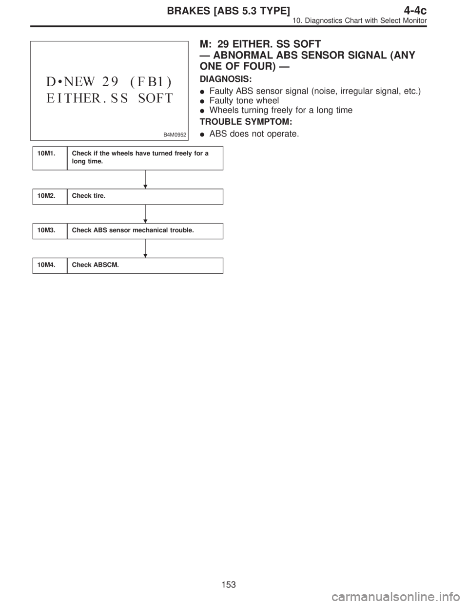
B4M0952
M: 29 EITHER. SS SOFT
—ABNORMAL ABS SENSOR SIGNAL (ANY
ONE OF FOUR)—
DIAGNOSIS:
�Faulty ABS sensor signal (noise, irregular signal, etc.)
�Faulty tone wheel
�Wheels turning freely for a long time
TROUBLE SYMPTOM:
�ABS does not operate.
10M1.Check if the wheels have turned freely for a
long time.
10M2.Check tire.
10M3.Check ABS sensor mechanical trouble.
10M4.Check ABSCM.
�
�
�
153
4-4cBRAKES [ABS 5.3 TYPE]
10. Diagnostics Chart with Select Monitor
Page 2495 of 2890
10M2
CHECK TIRE.
: Are the tire specifications correct?
: Go to next.
: Replace tire.
: Is the tire worn excessively?
: Replace tire.
: Go to next.
: Is the tire pressure correct?
: Go to step10M3.
: Adjust tire pressure.
10M3CHECK ABS SENSOR MECHANICAL
TROUBLE.
: Tightening torque:
32±10 N⋅m (3.3±1.0 kg-m, 24±7 ft-lb)
Are the ABS sensor installation bolts tight-
ened securely?
: Go to next.
: Tighten ABS sensor installation bolts securely.
: Tightening torque:
13±3 N⋅m (1.3±0.3 kg-m, 9±2.2 ft-lb)
Are the ABS sensor installation bolts tight-
ened securely?
: Go to next step.
: Tighten ABS sensor installation bolts securely.
G4M0700
1) Measure tone wheel to pole piece gap over entire
perimeter of the wheel.
: Is the gap within the specifications shown
in the following table?
SpecificationsFront wheel Rear wheel
0.9—1.4 mm
(0.035—0.055 in)0.7—1.2 mm
(0.028—0.047 in)
155
4-4cBRAKES [ABS 5.3 TYPE]
10. Diagnostics Chart with Select Monitor
 No. 1—Chassis ground
24/to (B15) No")
 No. 14—Chassis ground
24/(F49) No. 49—Ch")