Page 799 of 2890
 Install differential assembly�3on left hand transmission
case.
CAUTION:
Be careful not to fold the sealing lip of oil seal.
NOTE:
Wrap the left and right splined sections of axle shaft with")
G3M0557
3) Install differential assembly�3on left hand transmission
case.
CAUTION:
Be careful not to fold the sealing lip of oil seal.
NOTE:
Wrap the left and right splined sections of axle shaft with
vinyl tape to prevent scratches.
G3M0558
4) Install needle bearing and oil seal onto the front of
transmission main shaft assembly�
4, and position in left
side transmission case.
CAUTION:
�Wrap clutch splined section with vinyl tape to pre-
vent damage to oil seal.
�Apply grease (Unilube #2 or equivalent) to the seal-
ing lip of oil seal.
NOTE:
�Align the end face of seal with surface A of left side
transmission main case when installing oil seal.
�Be careful not to drop oil seal when installing right side
transmission main case.
�Make sure straight pin is positioned in hole in needle
bearing’s outer race.
G3M0575
5) Install drive pinion shaft assembly�5with shims
selected before into transmission case.
NOTE:
Ensure that the knock pin of the case is fitted into the hole
in the bearing outer race.
43
3-1SERVICE PROCEDURE
4. Transmission Case
Page 806 of 2890

A: DISASSEMBLY
1. DRIVE PINION SHAFT
1) Straighten lock nut at staked portion. Remove the lock
nut using ST1, ST2 and ST3.
ST1 899884100 HOLDER
ST2 4984271")
G3M0595
5. Drive Pinion Assembly (AWD Model)
A: DISASSEMBLY
1. DRIVE PINION SHAFT
1) Straighten lock nut at staked portion. Remove the lock
nut using ST1, ST2 and ST3.
ST1 899884100 HOLDER
ST2 498427100 STOPPER
ST3 899988608 SOCKET WRENCH
G3M0606
2) Withdraw drive pinion from driven shaft.
Remove differential bevel gear sleeve�
1, adjusting washer
No. 1�
2(25 x 37.5 x t), adjusting washer No. 2�3(25 x
37.5 x 4), thrust bearing�
4(25 x 37.5 x 3), needle bearing
�
5(25 x 30 x 20), drive pinion collar�6, needle bearing�7
(30 x 37 x 23) and thrust bearing�8(33x50x3).
G3M0607
3) Remove roller bearing and washer (33 x 50 x 5) using
ST and press.
ST 498077000 REMOVER
CAUTION:
Do not reuse roller bearing.
G3M0608
2. DRIVEN GEAR ASSEMBLY
CAUTION:
Attach a cloth to the end of driven shaft (on the fric-
tional side of thrust needle bearing) during disassem-
bly or reassembly to prevent damage.
1) Straighten lock nut at staked portion. Remove the lock
nut using ST1 and ST2.
ST1 499987300 SOCKET WRENCH (50)
ST2 899884100 HOLDER
G3M0609
2) Remove 5th driven gear using ST.
ST 499857000 5TH DRIVEN GEAR REMOVER
50
3-1SERVICE PROCEDURE
5. Drive Pinion Assembly (AWD Model)
Page 810 of 2890
 Install drive pinion collar�5, needle bearing�6(25x30
x 20), adjusting washer No. 2�
7(25 x 36 x 4), thrust bear-
ing�
8(25 x 37.5 x 3), adjusting washer No. 1�9(25x36
x t) and differentia")
B3M0083A
3) Install drive pinion collar�5, needle bearing�6(25x30
x 20), adjusting washer No. 2�
7(25 x 36 x 4), thrust bear-
ing�
8(25 x 37.5 x 3), adjusting washer No. 1�9(25x36
x t) and differential bevel gear sleeve�
10in that order.
NOTE:
Be careful because spacer must be installed in proper
direction.
�
A: Driven shaft
�
B: Driven pinion shaft
B3M0084A
G3M0625
4. ADJUSTMENT OF THRUST BEARING PRELOAD
1) After completing the preceding steps 1) through 3),
select adjusting washer No. 2 so that dimension�
His zero
through visual check. Position washer (18.3 x 30 x 4) and
lock washer (18 x 30 x 2) and install lock nut (18 x 13.5).
G3M0626
2) Using ST1, ST2 and ST3, tighten lock nut to the speci-
fied torque.
ST1 899884100 HOLDER
ST2 498427100 STOPPER
ST3 899988608 SOCKET WRENCH (27)
Tightening torque:
118±8 N⋅m (12±0.8 kg-m, 86.8±5.8 ft-lb)
B3M0085A
3) After removing ST2, measure starting torque using
torque driver.
ST1 899884100 HOLDER
ST3 899988608 SOCKET WRENCH (27)
Starting torque:
54±25 N⋅m (5.5±2.5 kg-m, 40±18 ft-lb)
54
3-1SERVICE PROCEDURE
5. Drive Pinion Assembly (AWD Model)
Page 819 of 2890
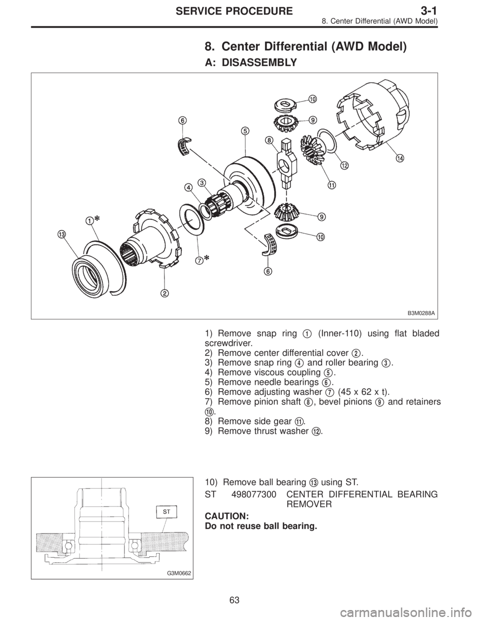
8. Center Differential (AWD Model)
A: DISASSEMBLY
B3M0288A
1) Remove snap ring�1(Inner-110) using flat bladed
screwdriver.
2) Remove center differential cover�
2.
3) Remove snap ring�
4and roller bearing�3.
4) Remove viscous coupling�
5.
5) Remove needle bearings�
6.
6) Remove adjusting washer�
7(45x62xt).
7) Remove pinion shaft�
8, bevel pinions�9and retainers
�
10.
8) Remove side gear�
11.
9) Remove thrust washer�
12.
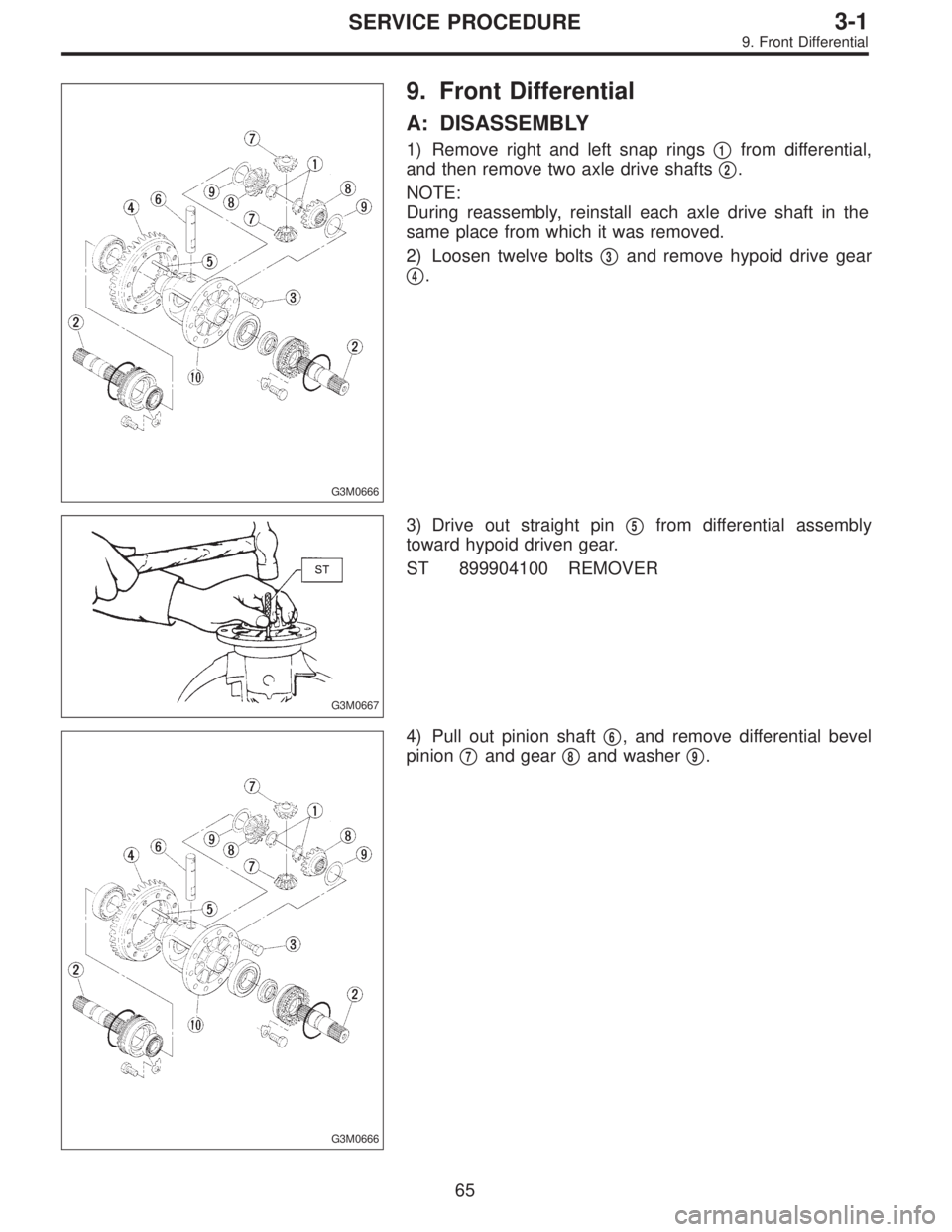
G3M0662
10) Remove ball bearing�13using ST.
ST 498077300 CENTER DIFFERENTIAL BEARING
REMOVER
CAUTION:
Do not reuse ball bearing.
63
3-1SERVICE PROCEDURE
8. Center Differential (AWD Model)
Page 820 of 2890

B3M0337
B: ASSEMBLY
Assembly is in the reverse order of disassembly.
Do the following:
�Install thrust washer with chamfered side of inner perim-
eter facing the side gear.
�Install adjusting washer with chamfered side of inner
perimeter facing the viscous coupling using ST.
ST 499547300 INSTALLER SET
B3M0095A
1) Selection of snap ring (Inner-110)
(1) After assembling, using a thickness gauge mea-
sure clearance between snap ring�
1and center differ-
ential case.
Clearance:
0—0.15 mm (0—0.0059 in)
(2) If the measurement is not within the specification,
select suitable snap ring.
Snap ring (Inner-110)
Part No. Thickness mm (in)
805100061 2.10 (0.0827)
805100062 2.21 (0.0870)
805100063 2.32 (0.0913)
B3M0096A
2) Selection of adjusting washer (Backlash adjustment)
(1) After assembling, set up a ST1 and ST2 to end of
viscous coupling shaft. Move viscous coupling up and
down, and measure backlash in the axial direction.
ST1 498247001 MAGNET BASE
ST2 498247100 DIAL GAUGE
Backlash:
0.62—0.86 mm (0.0244—0.0339 in)
(2) If the measurement is not within the specification,
select suitable washer.
Adjusting washer (45 x 62 x t)
Part No. Thickness mm (in)
803045041 1.60 (0.0630)
803045042 1.80 (0.0709)
803045043 2.00 (0.0787)
803045044 2.20 (0.0866)
803045045 2.40 (0.0945)
64
3-1SERVICE PROCEDURE
8. Center Differential (AWD Model)
Page 821 of 2890
G3M0666
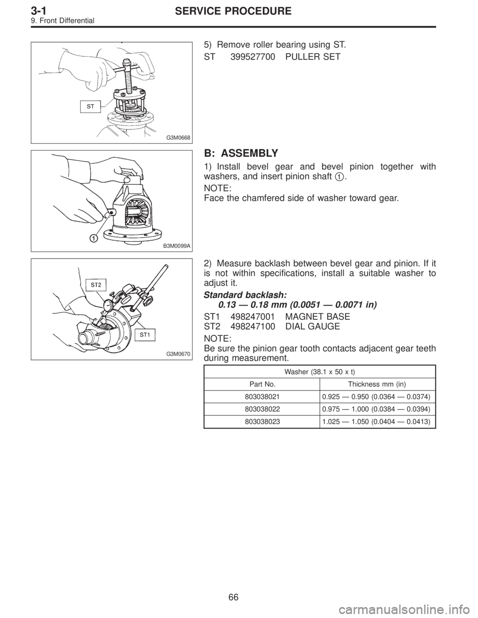
9. Front Differential
A: DISASSEMBLY
1) Remove right and left snap rings�1from differential,
and then remove two axle drive shafts�
2.
NOTE:
During reassembly, reinstall each axle drive shaft in the
same place from which it was removed.
2) Loosen twelve bolts�
3and remove hypoid drive gear
�
4.
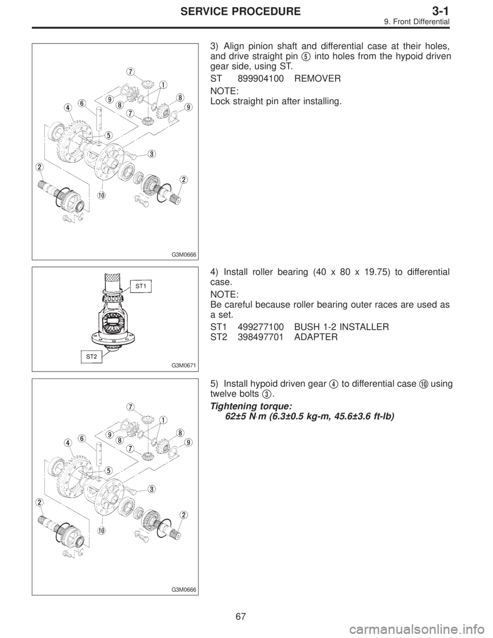
G3M0667
3) Drive out straight pin�5from differential assembly
toward hypoid driven gear.
ST 899904100 REMOVER
G3M0666
4) Pull out pinion shaft�6, and remove differential bevel
pinion�
7and gear�8and washer�9.
65
3-1SERVICE PROCEDURE
9. Front Differential
Page 822 of 2890
G3M0668
5) Remove roller bearing using ST.
ST 399527700 PULLER SET
B3M0099A
B: ASSEMBLY
1) Install bevel gear and bevel pinion together with
washers, and insert pinion shaft�
1.
NOTE:
Face the chamfered side of washer toward gear.
G3M0670
2) Measure backlash between bevel gear and pinion. If it
is not within specifications, install a suitable washer to
adjust it.
Standard backlash:
0.13—0.18 mm (0.0051—0.0071 in)
ST1 498247001 MAGNET BASE
ST2 498247100 DIAL GAUGE
NOTE:
Be sure the pinion gear tooth contacts adjacent gear teeth
during measurement.
Washer (38.1 x 50 x t)
Part No. Thickness mm (in)
803038021 0.925—0.950 (0.0364—0.0374)
803038022 0.975—1.000 (0.0384—0.0394)
803038023 1.025—1.050 (0.0404—0.0413)
66
3-1SERVICE PROCEDURE
9. Front Differential
Page 823 of 2890
G3M0666
3) Align pinion shaft and differential case at their holes,
and drive straight pin�
5into holes from the hypoid driven
gear side, using ST.
ST 899904100 REMOVER
NOTE:
Lock straight pin after installing.
G3M0671
4) Install roller bearing (40 x 80 x 19.75) to differential
case.
NOTE:
Be careful because roller bearing outer races are used as
a set.
ST1 499277100 BUSH 1-2 INSTALLER
ST2 398497701 ADAPTER
G3M0666
5) Install hypoid driven gear�4to differential case�10using
twelve bolts�
3.
Tightening torque:
62±5 N⋅m (6.3±0.5 kg-m, 45.6±3.6 ft-lb)
67
3-1SERVICE PROCEDURE
9. Front Differential