Page 769 of 2890
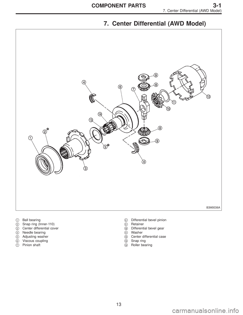
7. Center Differential (AWD Model)
B3M0036A
�1Ball bearing
�
2Snap ring (Inner-110)
�
3Center differential cover
�
4Needle bearing
�
5Adjusting washer
�
6Viscous coupling
�
7Pinion shaft�
8Differential bevel pinion
�
9Retainer
�
10Differential bevel gear
�
11Washer
�
12Center differential case
�
13Snap ring
�
14Roller bearing
13
3-1COMPONENT PARTS
7. Center Differential (AWD Model)
Page 770 of 2890
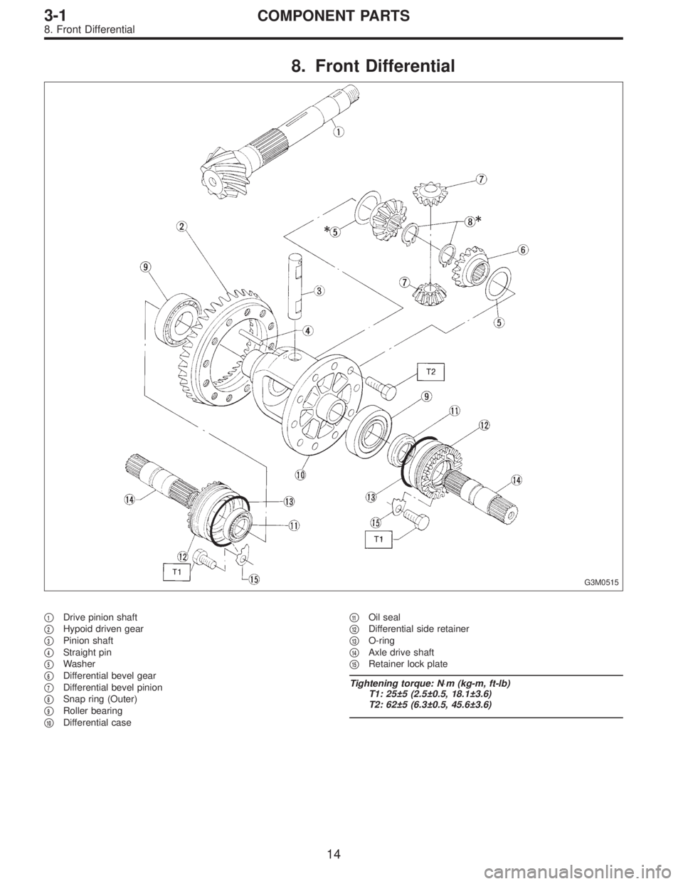
8. Front Differential
G3M0515
�1Drive pinion shaft
�
2Hypoid driven gear
�
3Pinion shaft
�
4Straight pin
�
5Washer
�
6Differential bevel gear
�
7Differential bevel pinion
�
8Snap ring (Outer)
�
9Roller bearing
�
10Differential case�
11Oil seal
�
12Differential side retainer
�
13O-ring
�
14Axle drive shaft
�
15Retainer lock plate
Tightening torque: N⋅m (kg-m, ft-lb)
T1: 25±5 (2.5±0.5, 18.1±3.6)
T2: 62±5 (6.3±0.5, 45.6±3.6)
14
3-1COMPONENT PARTS
8. Front Differential
Page 771 of 2890
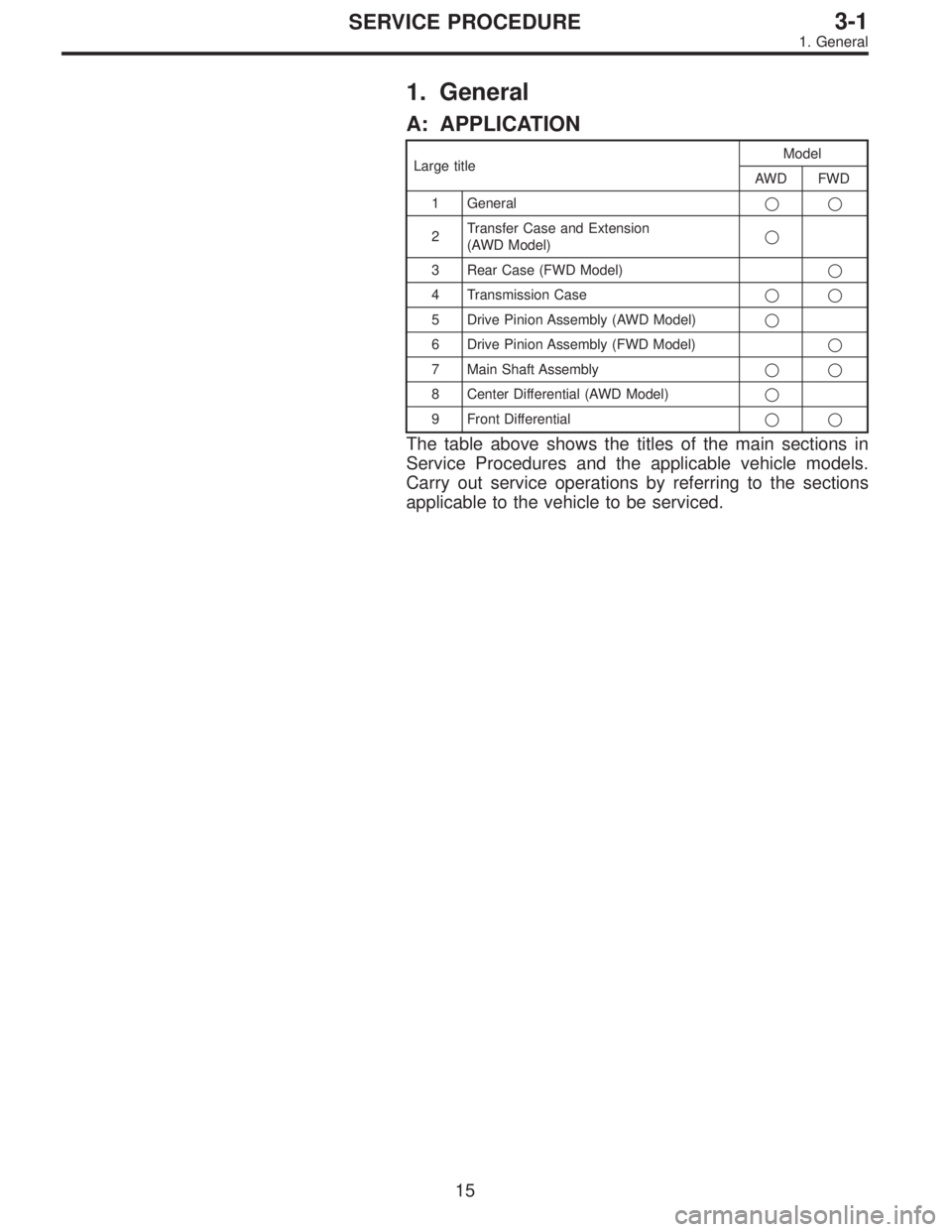
1. General
A: APPLICATION
Large titleModel
AWD FWD
1 General��
2Transfer Case and Extension
(AWD Model)�
3 Rear Case (FWD Model)�
4 Transmission Case��
5 Drive Pinion Assembly (AWD Model)�
6 Drive Pinion Assembly (FWD Model)�
7 Main Shaft Assembly��
8 Center Differential (AWD Model)�
9 Front Differential��
The table above shows the titles of the main sections in
Service Procedures and the applicable vehicle models.
Carry out service operations by referring to the sections
applicable to the vehicle to be serviced.
15
3-1SERVICE PROCEDURE
1. General
Page 774 of 2890
6) Oil seal
Replace the oil seal if the lip is deformed, hardened,
damaged, worn, or defective in any way.
7) O-ring
Replace the O-ring if the sealing face is deformed,
hardened, damaged, worn, or defective in any way.
8) Gearshift mechanism
Repair or replace the gearshift mechanism if excessively
worn, bent, or defective in any way.
G3M0521
9) Differential gear
Repair or replace the differential gear in the following
cases:
(1) The hypoid drive gear and drive pinion shaft tooth
surface are damaged, excessively worn, or seized.
(2) The roller bearing on the drive pinion shaft has a
worn or damaged roller path.
(3) There is damage, wear, or seizure of the differen-
tial bevel pinion, differential bevel gear, washer, pinion
shaft, and straight pin.
(4) The differential case has worn or damaged sliding
surfaces.
18
3-1SERVICE PROCEDURE
1. General
Page 776 of 2890
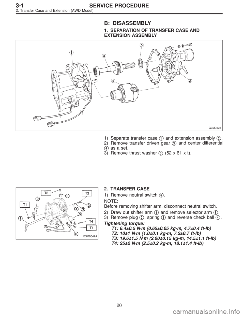
B: DISASSEMBLY
1. SEPARATION OF TRANSFER CASE AND
EXTENSION ASSEMBLY
G3M0523
1) Separate transfer case�1and extension assembly�2.
2) Remove transfer driven gear�
3and center differential
�
4as a set.
3) Remove thrust washer�
5(52x61xt).
B3M0042A
2. TRANSFER CASE
1) Remove neutral switch�
6.
NOTE:
Before removing shifter arm, disconnect neutral switch.
2) Draw out shifter arm�
1and remove selector arm�8.
3) Remove plug�
2, spring�3and reverse check ball�4.
Tightening torque:
T1: 6.4±0.5 N⋅m (0.65±0.05 kg-m, 4.7±0.4 ft-lb)
T2: 10±1 N⋅m (1.0±0.1 kg-m, 7.2±0.7 ft-lb)
T3: 19.6±1.5 N⋅m (2.00±0.15 kg-m, 14.5±1.1 ft-lb)
T4: 25±2 N⋅m (2.5±0.2 kg-m, 18.1±1.4 ft-lb)
20
3-1SERVICE PROCEDURE
2. Transfer Case and Extension (AWD Model)
Page 782 of 2890
 Installation of shifter arm�1and selector arm�8
Install shifter arm into the partition from the front while
inserting selector arm into the opening in reverse check
sleeve. Pass shaft thro")
B3M0042A
2) Installation of shifter arm�1and selector arm�8
Install shifter arm into the partition from the front while
inserting selector arm into the opening in reverse check
sleeve. Pass shaft through hole in selector arm until its end
comes out of the rear of transfer case.
NOTE:
Apply a coat of gear oil to shifter arm. Also make sure oil
seal is positioned properly.
Tightening torque:
T1: 6.4±0.5 N⋅m (0.65±0.05 kg-m, 4.7±0.4 ft-lb)
T2: 10±1 N⋅m (1.0±0.1 kg-m, 7.2±0.7 ft-lb)
T3: 19.6±1.5 N⋅m (2.00±0.15 kg-m, 14.5±1.1 ft-lb)
T4: 25±2 N⋅m (2.5±0.2 kg-m, 18.1±1.4 ft-lb)
B3M0049A
3. COMBINATION OF TRANSFER CASE AND
EXTENSION ASSEMBLY
1) Install center differential�
1and transfer driven gear�2
into transfer case.
Tightening torque:
T: 37±3 N⋅m (3.8±0.3 kg-m, 27.5±2.2 ft-lb)
B3M0050A
2) Selection of thrust washer (52 x 61 x t)
(1) Measure height“W”between transfer case and ball
bearing on the transfer driven gear�
3.
26
3-1SERVICE PROCEDURE
2. Transfer Case and Extension (AWD Model)
Page 790 of 2890
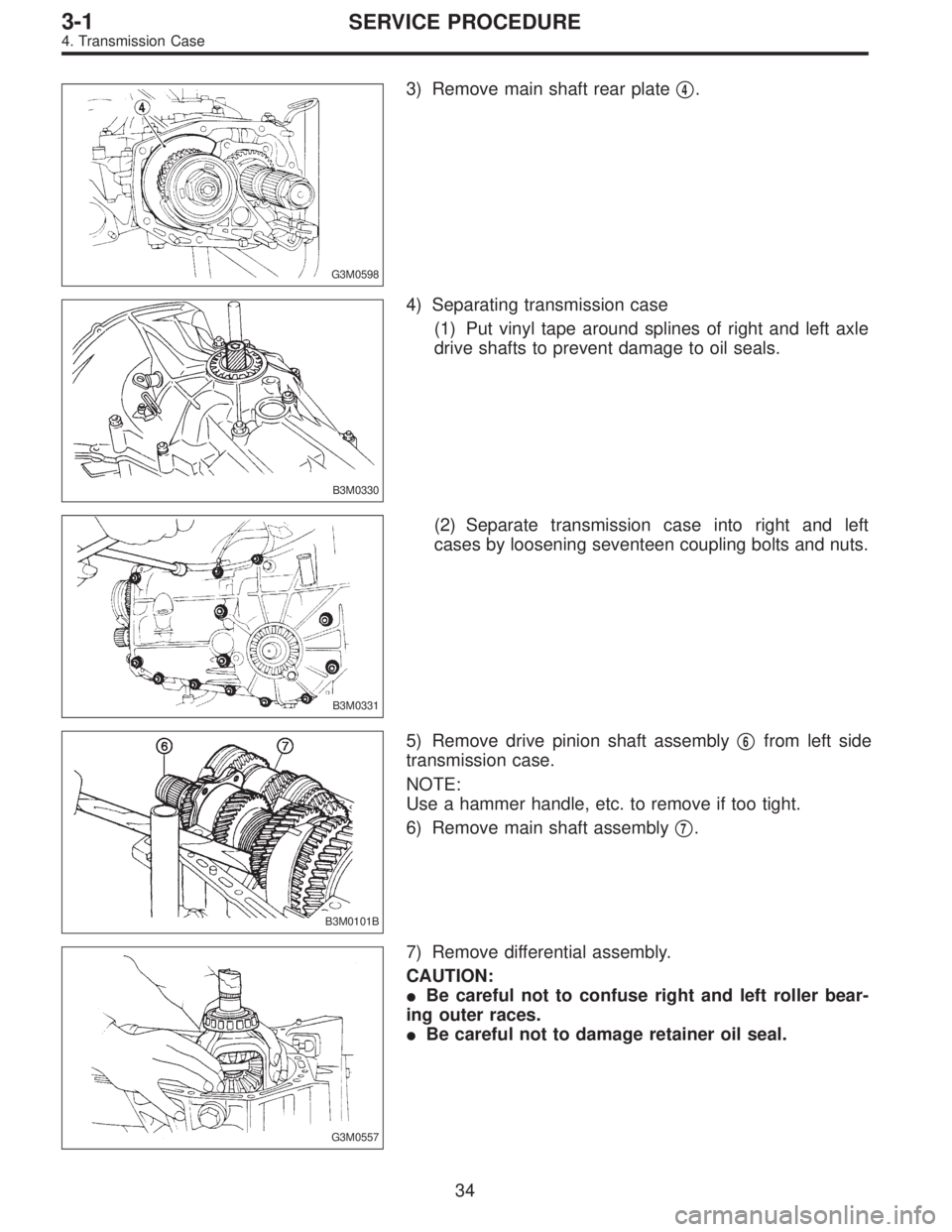
G3M0598
3) Remove main shaft rear plate�4.
B3M0330
4) Separating transmission case
(1) Put vinyl tape around splines of right and left axle
drive shafts to prevent damage to oil seals.
B3M0331
(2) Separate transmission case into right and left
cases by loosening seventeen coupling bolts and nuts.
B3M0101B
5) Remove drive pinion shaft assembly�6from left side
transmission case.
NOTE:
Use a hammer handle, etc. to remove if too tight.
6) Remove main shaft assembly�
7.
G3M0557
7) Remove differential assembly.
CAUTION:
�Be careful not to confuse right and left roller bear-
ing outer races.
�Be careful not to damage retainer oil seal.
34
3-1SERVICE PROCEDURE
4. Transmission Case
Page 792 of 2890
 Drive out spring pin�6, and pull out 3-4 fork rod�7and
shifter fork�
8.
NOTE:
When removing rod, keep other rods in neutral. Also, when
pulling out straight pin, remove it toward inside of")
B3M0333B
3) Drive out spring pin�6, and pull out 3-4 fork rod�7and
shifter fork�
8.
NOTE:
When removing rod, keep other rods in neutral. Also, when
pulling out straight pin, remove it toward inside of case so
that it may not hit against case.
4) Drive out straight pin�
9, and pull out 1-2 fork rod�10and
shifter fork�
11.
G3M0602
5) Pull out straight pin�12, and remove idler gear shaft�13,
reverse idler gear�
14and washer�15.
6) Remove outer snap ring�
16, and pull out reverse shifter
rod arm�
17from reverse fork rod�18. Then take out ball,
spring and interlock plunger from rod.
And then remove rod.
NOTE:
When pulling out reverse shifter rod arm, be careful not to
let ball pop out of arm.
7) Remove reverse shifter lever�
19.
G3M0546
8) Remove differential side retainers using ST.
ST 499787000 WRENCH ASSY
G3M0547
9) Remove outer snap ring�20and pull out speedometer
driven gear�
21. Next, remove vehicle speed sensor 2, oil
seal, speedometer shaft�
22and washer.
36
3-1SERVICE PROCEDURE
4. Transmission Case
 Oil seal
Replace the oil seal if the lip is deformed, hardened,
damaged, worn, or defective in any way.
7) O-ring
Replace the O-ring if the sealing face is deformed,
hardened, damaged, worn, or def")