Page 936 of 2890
G3M0488
14. Differential Case Assembly
A: DISASSEMBLY
1) Using a press and ST, remove the taper roller bearing.
ST 498077000 REMOVER
CAUTION:
Be careful not to damage the speedometer drive gear.
G3M0489
2) Secure the case in a vise and remove the crown gear
tightening bolts, then separate the crown gear, case (RH)
and case (LH).
G3M0490
3) Pull out the straight pin and shaft, and remove the dif-
ferential bevel gear, washer, and differential bevel pinion.
B: INSPECTION
Check each component for harmful cuts, damage and
other faults.
G3M0490
C: ASSEMBLY
1) Install the washer, differential bevel gear and differen-
tial bevel pinion in the differential case (RH). Insert the
pinion shaft, and fit the straight pin.
NOTE:
Install straight pin from reverse direction.
107
3-2SERVICE PROCEDURE
14. Differential Case Assembly
Page 937 of 2890
G3M0489
2) Install the washer and differential bevel gear to the dif-
ferential case (LH). Then put the case over the differential
case (RH), and connect both cases.
3) Install the crown gear and secure by tightening the bolt.
Standard tightening torque:
62±5 N⋅m (6.3±0.5 kg-m, 45.6±3.6 ft-lb)
G3M0491
4) Measurement of backlash (Selection of washer)
Measure the gear backlash with ST1 and ST2, and insert
ST2 through the access window of the case.
ST1 498247001 MAGNET BASE
ST2 498247100 DIAL GAUGE
Standard value:
0.13—0.18 mm (0.0051—0.0071 in)
NOTE:
Measure the backlash by applying a pinion tooth between
two bevel gear teeth.
G3M0492
5) Install the speedometer drive gear. Then force-fit the
taper roller bearing with a press and ST.
ST 398487700 DRIFT
CAUTION:
Be sure to position correctly the locking end of the
speedometer drive gear.
108
3-2SERVICE PROCEDURE
14. Differential Case Assembly
Page 961 of 2890
1. AWD System
A: SPECIFICATIONS
1. REAR FINAL REDUCTION GEAR RATIO
Type of gearHypoid
MT AT
2200 cc*2200 cc
OUTBACK2200 cc 2500 cc
Gear ratio
(Number of
gear teeth)3.900
(39/10)4 . 111
(37/9)4 . 111
(37/9)4.444
(40/9)
Oil capacity 0.8�(0.8 US qt, 0.7 Imp qt)
Rear
differential
gear oilGL-5
*: Step roof model only
2. PROPELLER SHAFT
Front propeller shaft
Joint-to-joint length:
L mm (in)AT 539 (21.22)
MT 598 (23.54)
Outside dia. of tube
mm (in)D
163.5 (2.500)
D
257.0 (2.244)
G3M0014
2
3-4SPECIFICATIONS AND SERVICE DATA
1. AWD System
Page 962 of 2890
G3M1049
B: IDENTIFICATION
When replacing a rear differential assembly, select the cor-
rect one according to the following table.
CAUTION:
Using the different rear differential assembly causes
the drive line and tires to “drag” or emit abnormal
noise when AWD is selected.
Gear ratio Part number Label stuck on rear differential
2200 cc
MT3.900 38369AA450
B3M0124
2200 cc
AT
4.111 38369AA460
B3M0127
*2200 cc
OUTBACK
MT
2500 cc
AT4.444 38369AA510
B3M0421
*: Step roof model only
3
3-4SPECIFICATIONS AND SERVICE DATA
1. AWD System
Page 965 of 2890
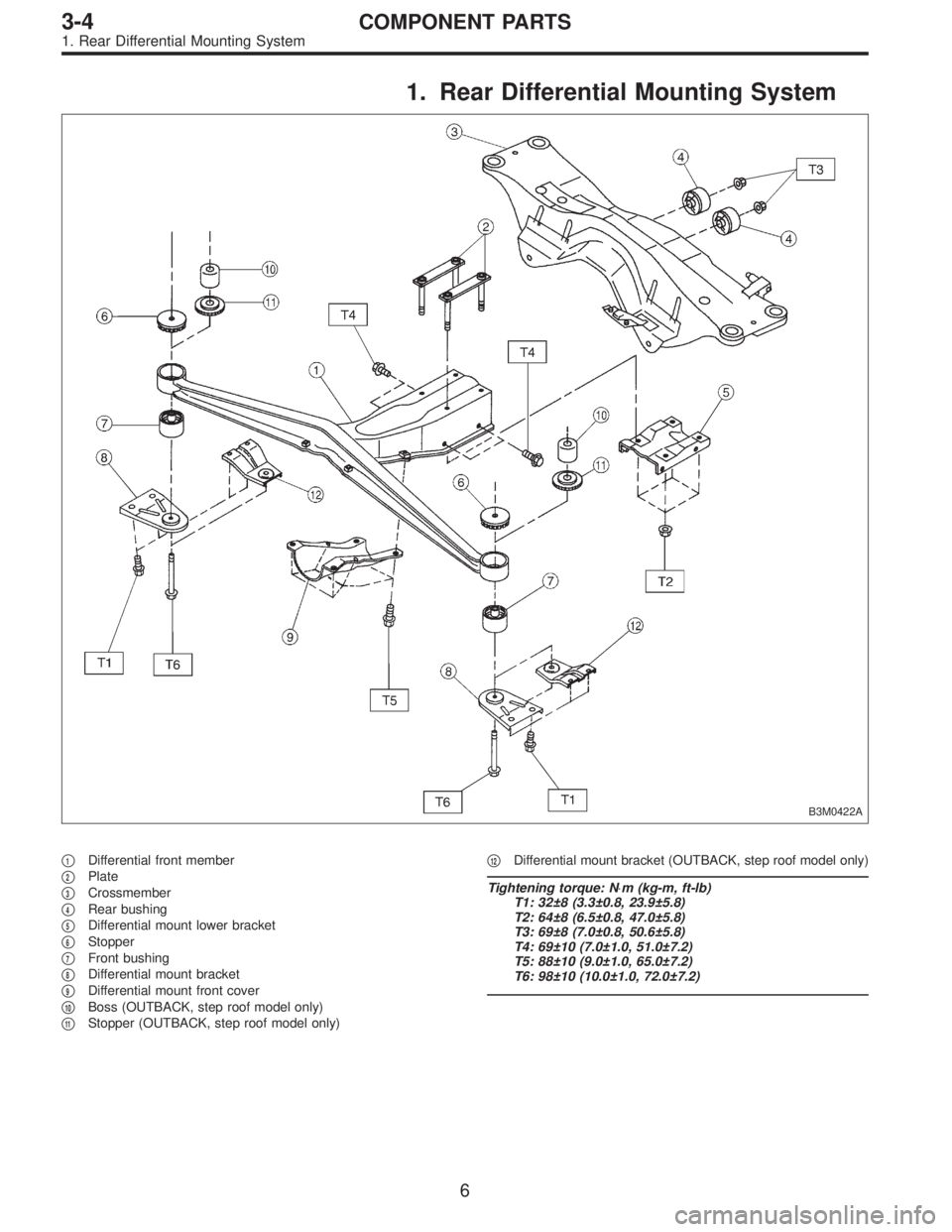
1. Rear Differential Mounting System
B3M0422A
�1Differential front member
�
2Plate
�
3Crossmember
�
4Rear bushing
�
5Differential mount lower bracket
�
6Stopper
�
7Front bushing
�
8Differential mount bracket
�
9Differential mount front cover
�
10Boss (OUTBACK, step roof model only)
�
11Stopper (OUTBACK, step roof model only)�
12Differential mount bracket (OUTBACK, step roof model only)
Tightening torque: N⋅m (kg-m, ft-lb)
T1: 32±8 (3.3±0.8, 23.9±5.8)
T2: 64±8 (6.5±0.8, 47.0±5.8)
T3: 69±8 (7.0±0.8, 50.6±5.8)
T4: 69±10 (7.0±1.0, 51.0±7.2)
T5: 88±10 (9.0±1.0, 65.0±7.2)
T6: 98±10 (10.0±1.0, 72.0±7.2)
6
3-4COMPONENT PARTS
1. Rear Differential Mounting System
Page 966 of 2890
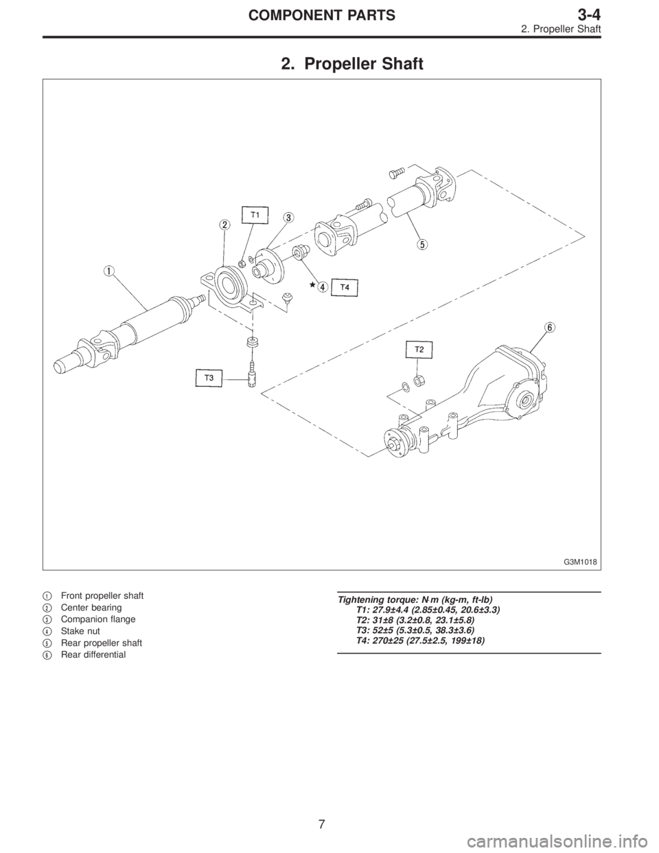
2. Propeller Shaft
G3M1018
�1Front propeller shaft
�
2Center bearing
�
3Companion flange
�
4Stake nut
�
5Rear propeller shaft
�
6Rear differential
Tightening torque: N⋅m (kg-m, ft-lb)
T1: 27.9±4.4 (2.85±0.45, 20.6±3.3)
T2: 31±8 (3.2±0.8, 23.1±5.8)
T3: 52±5 (5.3±0.5, 38.3±3.6)
T4: 270±25 (27.5±2.5, 199±18)
7
3-4COMPONENT PARTS
2. Propeller Shaft
Page 967 of 2890
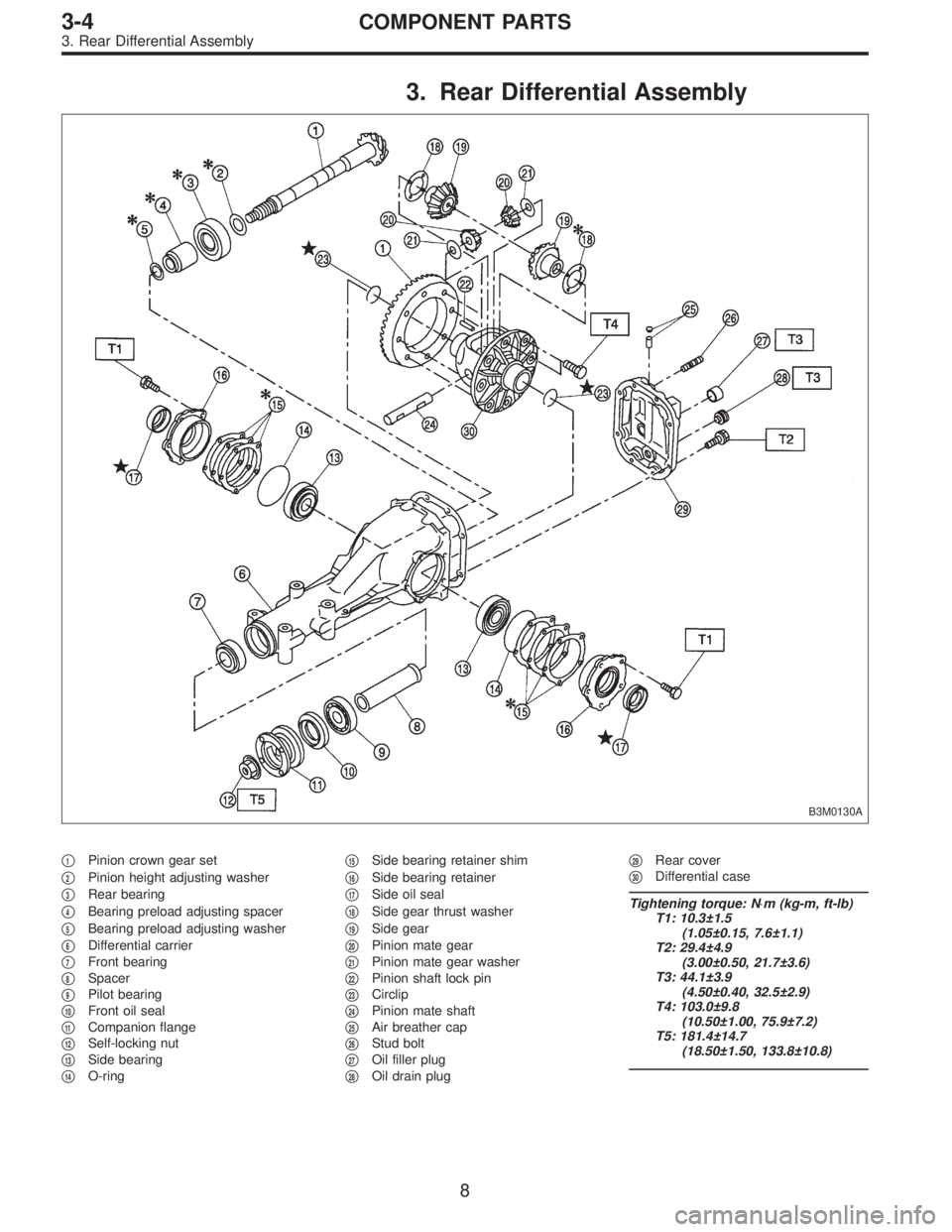
3. Rear Differential Assembly
B3M0130A
�1Pinion crown gear set
�
2Pinion height adjusting washer
�
3Rear bearing
�
4Bearing preload adjusting spacer
�
5Bearing preload adjusting washer
�
6Differential carrier
�
7Front bearing
�
8Spacer
�
9Pilot bearing
�
10Front oil seal
�
11Companion flange
�
12Self-locking nut
�
13Side bearing
�
14O-ring�
15Side bearing retainer shim
�
16Side bearing retainer
�
17Side oil seal
�
18Side gear thrust washer
�
19Side gear
�
20Pinion mate gear
�
21Pinion mate gear washer
�
22Pinion shaft lock pin
�
23Circlip
�
24Pinion mate shaft
�
25Air breather cap
�
26Stud bolt
�
27Oil filler plug
�
28Oil drain plug�
29Rear cover
�
30Differential case
Tightening torque: N⋅m (kg-m, ft-lb)
T1: 10.3±1.5
(1.05±0.15, 7.6±1.1)
T2: 29.4±4.9
(3.00±0.50, 21.7±3.6)
T3: 44.1±3.9
(4.50±0.40, 32.5±2.9)
T4: 103.0±9.8
(10.50±1.00, 75.9±7.2)
T5: 181.4±14.7
(18.50±1.50, 133.8±10.8)
8
3-4COMPONENT PARTS
3. Rear Differential Assembly
Page 969 of 2890
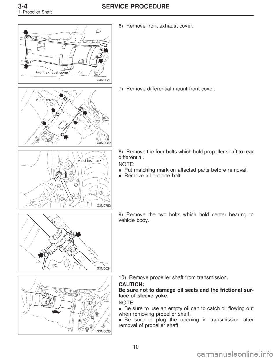
G3M0021
6) Remove front exhaust cover.
G3M0022
7) Remove differential mount front cover.
G3M0782
8) Remove the four bolts which hold propeller shaft to rear
differential.
NOTE:
�Put matching mark on affected parts before removal.
�Remove all but one bolt.
G3M0024
9) Remove the two bolts which hold center bearing to
vehicle body.
G3M0025
10) Remove propeller shaft from transmission.
CAUTION:
Be sure not to damage oil seals and the frictional sur-
face of sleeve yoke.
NOTE:
�Be sure to use an empty oil can to catch oil flowing out
when removing propeller shaft.
�Be sure to plug the opening in transmission after
removal of propeller shaft.
10
3-4SERVICE PROCEDURE
1. Propeller Shaft
 Using a press and ST, remove the taper roller bearing.
ST 498077000 REMOVER
CAUTION:
Be careful not to damage the speedometer drive gear.
G3M04")
 Install the washer and differential bevel gear to the dif-
ferential case (LH). Then put the case over the differential
case (RH), and connect both cases.
3) Install the crown gear and secu")
3.900
(39/10)4 . 111
(37/9)4 . 111
(")