Page 2410 of 2890
8I6CHECK POOR CONTACT IN CONNEC-
TOR BETWEEN AT CONTROL MODULE
AND ABSCM.
: Is there poor contact in connectors between
AT control module and ABSCM?
: Repair connector.
: Go to step8I7.
8I7
CHECK ABSCM.
1) Connect all connectors.
2) Erase the memory.
3) Perform inspection mode.
4) Read out the trouble code.
: Is the same trouble code as in the current
diagnosis still being output?
: Replace ABSCM.
: Go to next.
: Are other trouble codes being output?
: Proceed with the diagnosis corresponding to the
trouble code.
: A temporary poor contact.
70
4-4cBRAKES [ABS 5.3 TYPE]
8. Diagnostics Chart with Trouble Code
Page 2411 of 2890
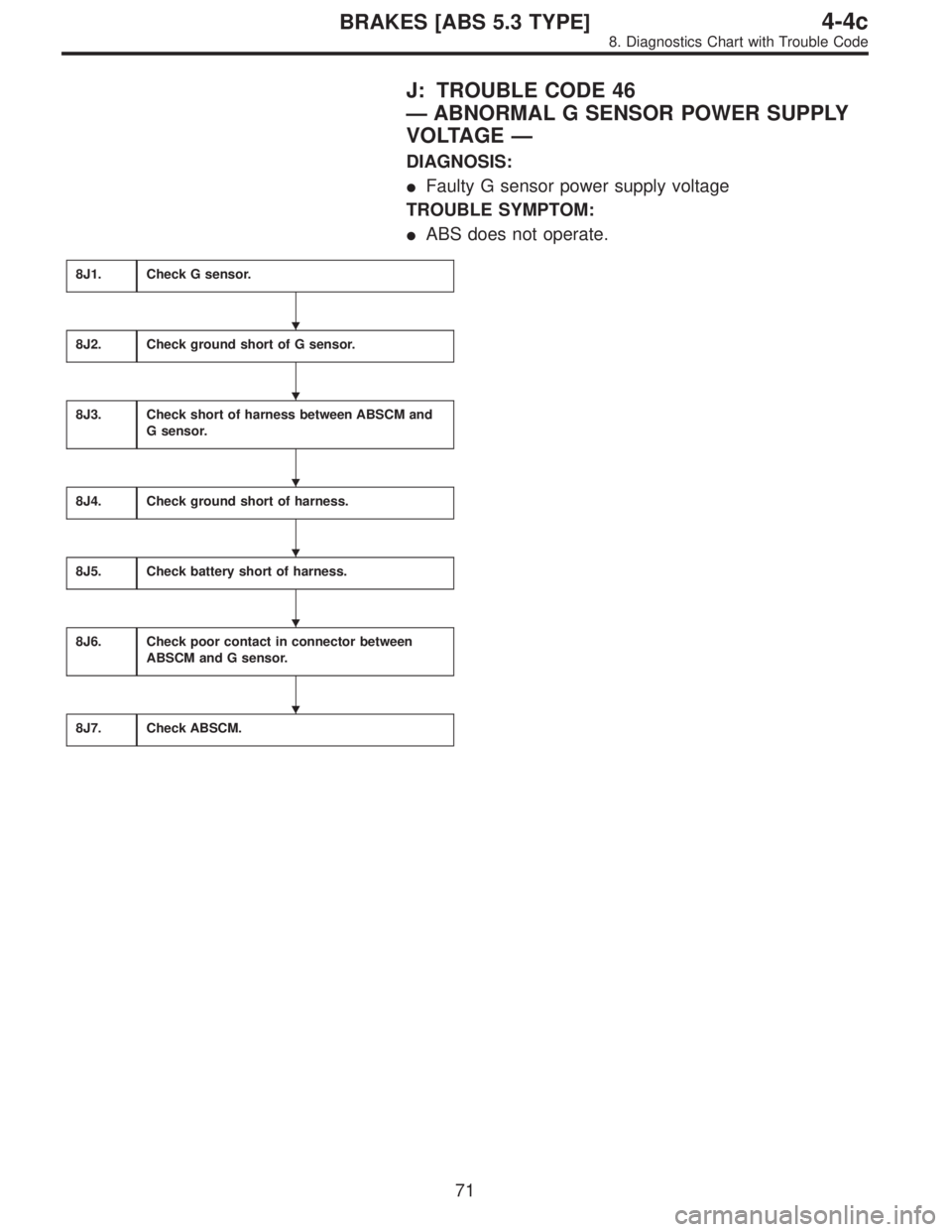
J: TROUBLE CODE 46
—ABNORMAL G SENSOR POWER SUPPLY
VOLTAGE—
DIAGNOSIS:
�Faulty G sensor power supply voltage
TROUBLE SYMPTOM:
�ABS does not operate.
8J1.Check G sensor.
8J2.Check ground short of G sensor.
8J3.Check short of harness between ABSCM and
G sensor.
8J4.Check ground short of harness.
8J5.Check battery short of harness.
8J6.Check poor contact in connector between
ABSCM and G sensor.
8J7.Check ABSCM.
�
�
�
�
�
�
71
4-4cBRAKES [ABS 5.3 TYPE]
8. Diagnostics Chart with Trouble Code
Page 2412 of 2890
WIRING DIAGRAM:
B4M1047
B4M0851B
8J1
CHECK G SENSOR.
1) Turn ignition switch to OFF.
2) Remove console box.
3) Disconnect connector from G sensor.
4) Measure resistance of G sensor.
: Connector & terminal
To (P11) No. 1—No. 3
Is resistance 50±8 kΩ?
: Go to step8J2.
: Replace G sensor.
72
4-4cBRAKES [ABS 5.3 TYPE]
8. Diagnostics Chart with Trouble Code
Page 2413 of 2890
B4M0852B
8J2
CHECK GROUND SHORT OF G SENSOR.
Measure resistance between G sensor and bracket.
: Connector & terminal
To (P11) No. 3—Bracket
Is resistance more than 1 MΩ?
: Go to step8J3.
: Replace G sensor.
B4M0853A
8J3CHECK SHORT OF HARNESS BETWEEN
ABSCM AND G SENSOR.
1) Disconnect connector from ABSCM.
2) Measure resistance between ABSCM connector termi-
nals.
: Connector & terminal
(F49) No. 45—No. 8
Is resistance more than 1 MΩ?
: Go to step8J4.
: Repair harness between ABSCM and G sensor.
B4M0854A
8J4
CHECK GROUND SHORT OF HARNESS.
Measure resistance between ABSCM connector and chas-
sis ground.
: Connector & terminal
(F49) No. 8—Chassis ground
(F49) No. 45—Chassis ground
Is resistance more than 1 MΩ?
: Go to step8J5.
: Repair harness between ABSCM and G sensor.
73
4-4cBRAKES [ABS 5.3 TYPE]
8. Diagnostics Chart with Trouble Code
Page 2414 of 2890
 Turn ignition switch to ON.
2) Measure voltage between ABSCM connector and chas-
sis ground.
: Connector & terminal
(F49) No. 8 (+)—Chassis ground (�)")
B4M0855A
8J5
CHECK BATTERY SHORT OF HARNESS.
1) Turn ignition switch to ON.
2) Measure voltage between ABSCM connector and chas-
sis ground.
: Connector & terminal
(F49) No. 8 (+)—Chassis ground (�)
(F49) No. 45 (+)—Chassis ground (�)
Is voltage 0 V?
: Go to next step.
: Repair harness between ABSCM and G sensor.
3) Turn ignition switch to OFF.
4) Measure voltage between ABSCM and chassis ground.
: Connector & terminal
(F49) No. 8 (+)—Chassis ground (�)
(F49) No. 45 (+)—Chassis ground (�)
Is voltage 0 V?
: Go to step8J6.
: Repair harness between ABSCM and chassis
ground.
8J6CHECK POOR CONTACT IN CONNEC-
TOR BETWEEN ABSCM AND G SENSOR.
: Is there poor contact in connectors between
ABSCM and G sensor?
: Repair connector.
: Go to step8J7.
8J7
CHECK ABSCM.
1) Connect all connectors.
2) Erase the memory.
3) Perform inspection mode.
4) Read out the trouble code.
: Is the same trouble code as in the current
diagnosis still being output?
: Replace ABSCM.
: Go to next.
: Are other trouble codes being output?
: Proceed with the diagnosis corresponding to the
trouble code.
: A temporary poor contact.
74
4-4cBRAKES [ABS 5.3 TYPE]
8. Diagnostics Chart with Trouble Code
Page 2415 of 2890

K: TROUBLE CODE 51
—ABNORMAL VALVE RELAY—
DIAGNOSIS:
�Faulty valve relay
TROUBLE SYMPTOM:
�ABS does not operate.
8K1.Check resistance of valve relay.
8K2.Check contact point of valve relay.
8K3.Check short of valve relay.
8K4.Check power supply voltage at valve relay
contact point.
8K5.Check ground circuit of relay box.
8K6.Check broken wire and ground short in power
supply circuit of relay box.
8K7.Check broken wire in contact point circuit of
relay box.
8K8.Check ground short in contact point circuit of
relay box.
8K9.Check battery short in contact point circuit of
relay box.
8K10.Check diode of relay box.
8K11.Check broken wire in ground circuit of relay
box.
8K12.Check battery short in ground circuit of relay
box.
8K13.Check broken wire in control circuit of relay
box.
8K14.Check ground short in control circuit of relay
box.
8K15.Check battery short in control circuit of relay
box.
Continues to next page.
�
�
�
�
�
�
�
�
�
�
�
�
�
�
�
75
4-4cBRAKES [ABS 5.3 TYPE]
8. Diagnostics Chart with Trouble Code
Page 2416 of 2890
From the former page.
8K16.
Check broken wire in control system harness
of valve relay.
8K17.Check ground short in control system harness
of valve relay.
8K18.Check battery short in control system harness
of valve relay.
8K19.Check resistance of inlet solenoid valve.
8K20.Check resistance of outlet solenoid valve.
8K21.Check ground short of solenoid valve.
8K22.Check battery short of solenoid valve.
8K23.Check battery short of harness.
8K24.Check ground short of harness.
8K25.Check harness connector between ABSCM
and hydraulic unit.
8K26.Check poor contact in connector between
ABSCM and hydraulic unit.
8K27.Check ABSCM.
�
�
�
�
�
�
�
�
�
�
�
�
76
4-4cBRAKES [ABS 5.3 TYPE]
8. Diagnostics Chart with Trouble Code
Page 2417 of 2890
WIRING DIAGRAM:
B4M1048
B4M0858A
8K1
CHECK RESISTANCE OF VALVE RELAY.
1) Turn ignition switch to OFF.
2) Remove valve relay from relay box.
3) Measure resistance between valve relay terminals.
: Terminals
No. 85—No. 86
Is resistance 103±10Ω?
: Go to step8K2.
: Replace valve relay.
77
4-4cBRAKES [ABS 5.3 TYPE]
8. Diagnostics Chart with Trouble Code

 Turn ignition switch to OFF.
2) Remove console box.
3) Disconnect connector from G sensor.
4) Measure resistance of G sensor.
: Connector & term")
 No. 3—Bracket
Is resistance more than 1 MΩ?
: Go to step8J3.
: Replace")

 Turn ignition switch to OFF.
2) Remove valve relay from relay box.
3) Measure resistance between valve relay terminals.
: Termi")