Page 729 of 2890
G2M0286
11) Remove power steering pump from bracket.
(1) Loosen lock bolt and slider bolt, and remove front
side V-belt.
B2M0340
(2) Remove pipe with bracket from intake manifold.
B2M0334
(3) Remove bolts which install power steering pump
from bracket.
B2M0029
(4) Place power steering pump on the right side wheel
apron.
G2M0290
12) Remove front exhaust pipe and center exhaust pipe.
(1) Lift-up the vehicle.
(2) Remove nuts which install front exhaust pipe onto
engine.
16
2-11SERVICE PROCEDURE
2. Engine
Page 864 of 2890

3. Performance Test
A: STALL TEST
1. GENERAL
The stall test is of extreme importance in diagnosing the
condition of the automatic transmission and the engine. It
should be conducted to measure the engine stall speeds in
all shift ranges except the P and N ranges.
Purposes of the stall test:
1) To check the operation of the automatic transmission
clutch.
2) To check the operation of the torque converter clutch.
3) To check engine performance.
2. TEST METHODS
Preparations before test:
�
1Check that throttle valve opens fully.
�
2Check that engine oil level is correct.
�
3Check that coolant level is correct.
�
4Check that ATF level is correct.
�
5Check that differential gear oil level is correct.
�
6Increase ATF temperature to 50 to 80°C (122 to 176°F)
by idling the engine for approximately 30 minutes (with
select lever set to“N”or“P”).
1) Install an engine tachometer at a location visible from
the driver’s compartment and mark the stall speed range
on the tachometer scale.
2) Place the wheel chocks at the front and rear of all
wheels and engage the parking brake.
3) Move the manual linkage to ensure it operates properly,
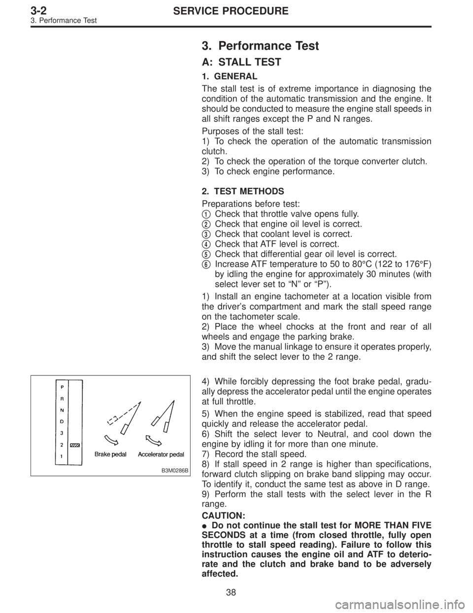
and shift the select lever to the 2 range.
B3M0286B
4) While forcibly depressing the foot brake pedal, gradu-
ally depress the accelerator pedal until the engine operates
at full throttle.
5) When the engine speed is stabilized, read that speed
quickly and release the accelerator pedal.
6) Shift the select lever to Neutral, and cool down the
engine by idling it for more than one minute.
7) Record the stall speed.
8) If stall speed in 2 range is higher than specifications,
forward clutch slipping on brake band slipping may occur.
To identify it, conduct the same test as above in D range.
9) Perform the stall tests with the select lever in the R
range.
CAUTION:
�Do not continue the stall test for MORE THAN FIVE
SECONDS at a time (from closed throttle, fully open
throttle to stall speed reading). Failure to follow this
instruction causes the engine oil and ATF to deterio-
rate and the clutch and brake band to be adversely
affected.
38
3-2SERVICE PROCEDURE
3. Performance Test
Page 867 of 2890

C: LINE PRESSURE TEST
1. GENERAL
If the clutch or the brake band shows a sign of slippage or
shifting sensation is not correct, the line pressure should be
checked.
�Excessive shocks during upshifting or shifting takes
place at a higher point than under normal circumstances,
may be due to the line pressure being too high.
�Slippage or inability to operate the vehicle may, in most
cases, be due to loss of oil pressure for the operation of
the clutch, brake band or control valve.
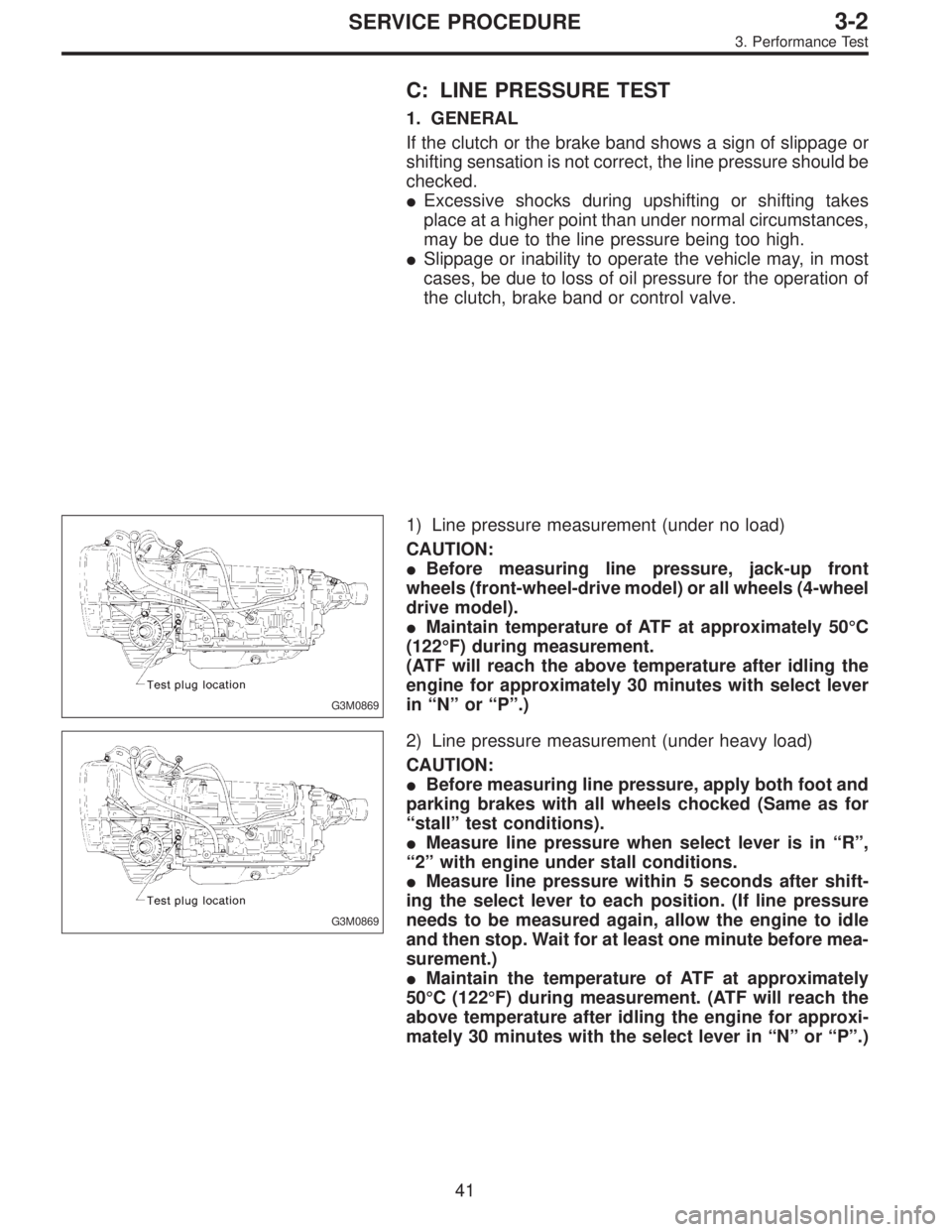
G3M0869
1) Line pressure measurement (under no load)
CAUTION:
�Before measuring line pressure, jack-up front
wheels (front-wheel-drive model) or all wheels (4-wheel
drive model).
�Maintain temperature of ATF at approximately 50°C
(122°F) during measurement.
(ATF will reach the above temperature after idling the
engine for approximately 30 minutes with select lever
in“N”or“P”.)
G3M0869
2) Line pressure measurement (under heavy load)
CAUTION:
�Before measuring line pressure, apply both foot and
parking brakes with all wheels chocked (Same as for
“stall”test conditions).
�Measure line pressure when select lever is in“R”,
“2”with engine under stall conditions.
�Measure line pressure within 5 seconds after shift-
ing the select lever to each position. (If line pressure
needs to be measured again, allow the engine to idle
and then stop. Wait for at least one minute before mea-
surement.)
�Maintain the temperature of ATF at approximately
50°C (122°F) during measurement. (ATF will reach the
above temperature after idling the engine for approxi-
mately 30 minutes with the select lever in“N”or“P”.)
41
3-2SERVICE PROCEDURE
3. Performance Test
Page 870 of 2890
4. CHECK FOR THE AWD FUNCTION
If“tight-corner braking”occurs when the steering wheel is
fully turned at low speed:
1) Determine the applicable trouble code and check the
corresponding duty solenoid C (transfer) for improper
operation.
2) If the solenoid is operating properly, check transfer
clutch pressure.
3) If oil pressure is normal but“tight-corner braking”
occurs:
Check the transfer control valve for sticking, and the trans-
fer clutch facing for wear.
44
3-2SERVICE PROCEDURE
3. Performance Test
Page 968 of 2890

1. Propeller Shaft
A: ON-CAR SERVICE
Check the following points with propeller shaft installed in
vehicle.
1) Joints and connections
Check for any looseness of yoke flange connecting bolts
and center bearing retaining bolts.
G3M0019
2) Splines and bearing locations
Turn propeller shaft by hand to see if abnormal free play
exists at splines. Also move yokes to see if abnormal free
play exists at spiders and bearings.
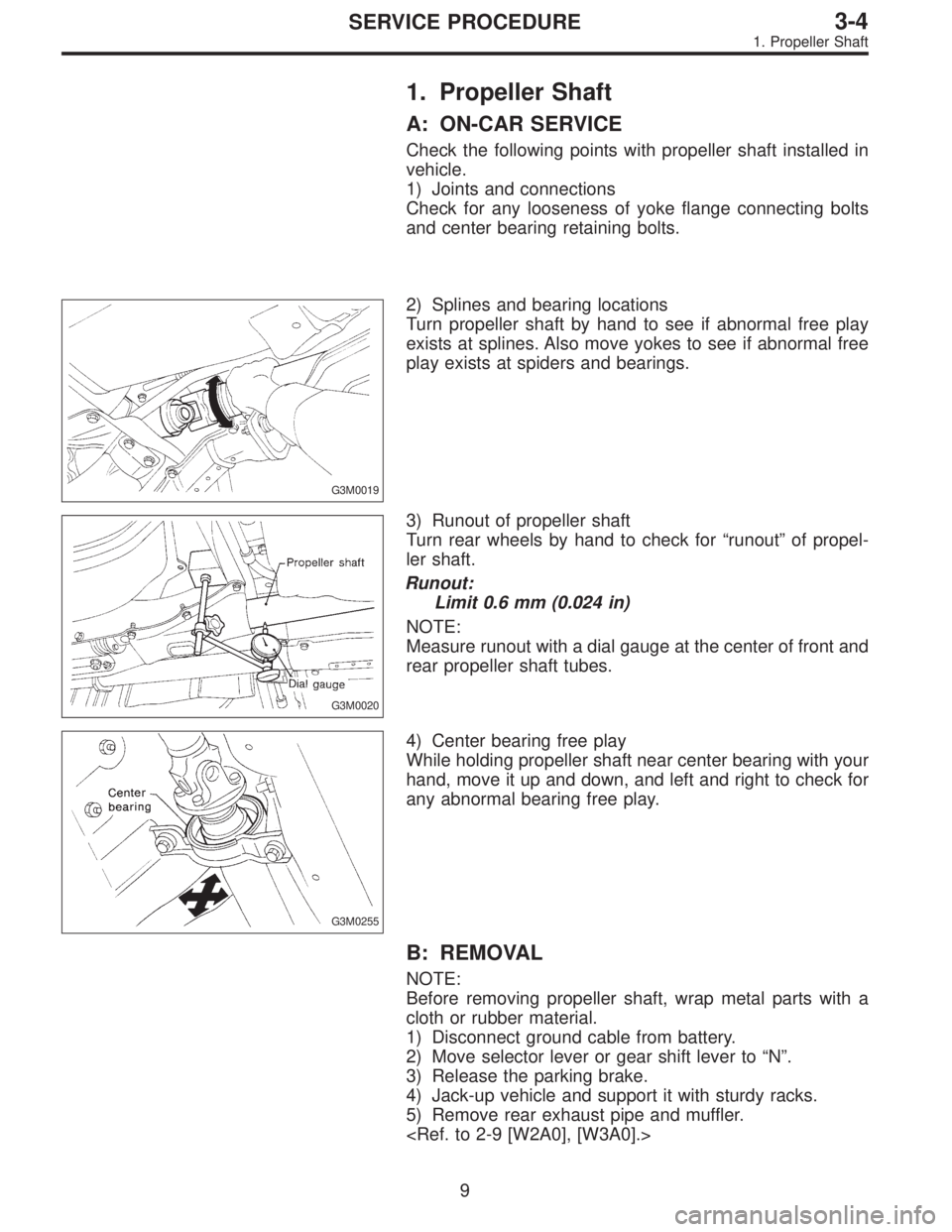
G3M0020
3) Runout of propeller shaft
Turn rear wheels by hand to check for“runout”of propel-
ler shaft.
Runout:
Limit 0.6 mm (0.024 in)
NOTE:
Measure runout with a dial gauge at the center of front and
rear propeller shaft tubes.
G3M0255
4) Center bearing free play
While holding propeller shaft near center bearing with your
hand, move it up and down, and left and right to check for
any abnormal bearing free play.
B: REMOVAL
NOTE:
Before removing propeller shaft, wrap metal parts with a
cloth or rubber material.
1) Disconnect ground cable from battery.
2) Move selector lever or gear shift lever to“N”.
3) Release the parking brake.
4) Jack-up vehicle and support it with sturdy racks.
5) Remove rear exhaust pipe and muffler.
9
3-4SERVICE PROCEDURE
1. Propeller Shaft
Page 973 of 2890
2. Rear Differential
A: ON-CAR SERVICE
1. FRONT OIL SEAL
1) Disconnect ground cable from battery.
2) Move selector lever or gear shift lever to“N”.
3) Release the parking brake.
B3M0316A
4) Remove oil drain plug, and drain gear oil.
G3M0024
5) Jack-up rear wheels and support the vehicle body with
sturdy racks.
6) Remove propeller shaft from body.
[W1B0].>
CAUTION:
Wrap metal parts with a cloth or rubber material to
prevent damage from adjacent metal parts.
G3M0034
7) Remove self-locking nut while holding companion
flange with ST.
ST 498427200 FLANGE WRENCH
G3M0035
8) Extract companion flange with a puller.
14
3-4SERVICE PROCEDURE
2. Rear Differential
Page 975 of 2890
2. SIDE OIL SEAL
1) Disconnect ground cable from battery.
2) Move selector lever or gear shift lever to“N”.
3) Release the parking brake.
4) Loosen both wheel nuts.
5) Jack-up the vehicle and support it with rigid racks.
6) Remove wheels.
7) Remove rear exhaust pipe and muffler.
G3M0038
8) Remove the DOJ of rear drive shaft from rear differen-
tial.
(1) Remove the A.B.S. sensor cable clamp and park-
ing brake cable clamp from bracket.
G3M0039
(2) Remove the A.B.S. sensor cable clamp from the
trailing link.
G3M0040
(3) Remove the A.B.S. sensor cable clamp and park-
ing brake cable guide from the trailing link.
G3M0041
(4) Remove the rear stabilizer link.
16
3-4SERVICE PROCEDURE
2. Rear Differential
Page 978 of 2890
B: REMOVAL
1) Disconnect ground cable from battery.
2) Move selector lever or gear shift lever to“N”.
3) Release the parking brake.
4) Loosen wheel nuts.
5) Jack-up vehicle and support it with sturdy racks.
6) Remove wheels.
7) Remove rear exhaust pipe and muffler.
G3M0021
8) Remove front exhaust cover.
G3M0022
9) Remove front cover of rear differential mount.
G3M0024
10) Remove propeller shaft.
CAUTION:
When removing propeller shaft, pay attention not to
damage the sliding surfaces of rear drive shaft (exten-
sion) spline, oil seal and sleeve yoke.
NOTE:
Prepare an oil can and cap since the transmission oil flows
out from the extension at removing propeller shaft.
G3M0026
NOTE:
Insert the cap into the extension to prevent transmission oil
from flowing out immediately after removing the propeller
shaft.
19
3-4SERVICE PROCEDURE
2. Rear Differential