Page 676 of 2890
G2M0360
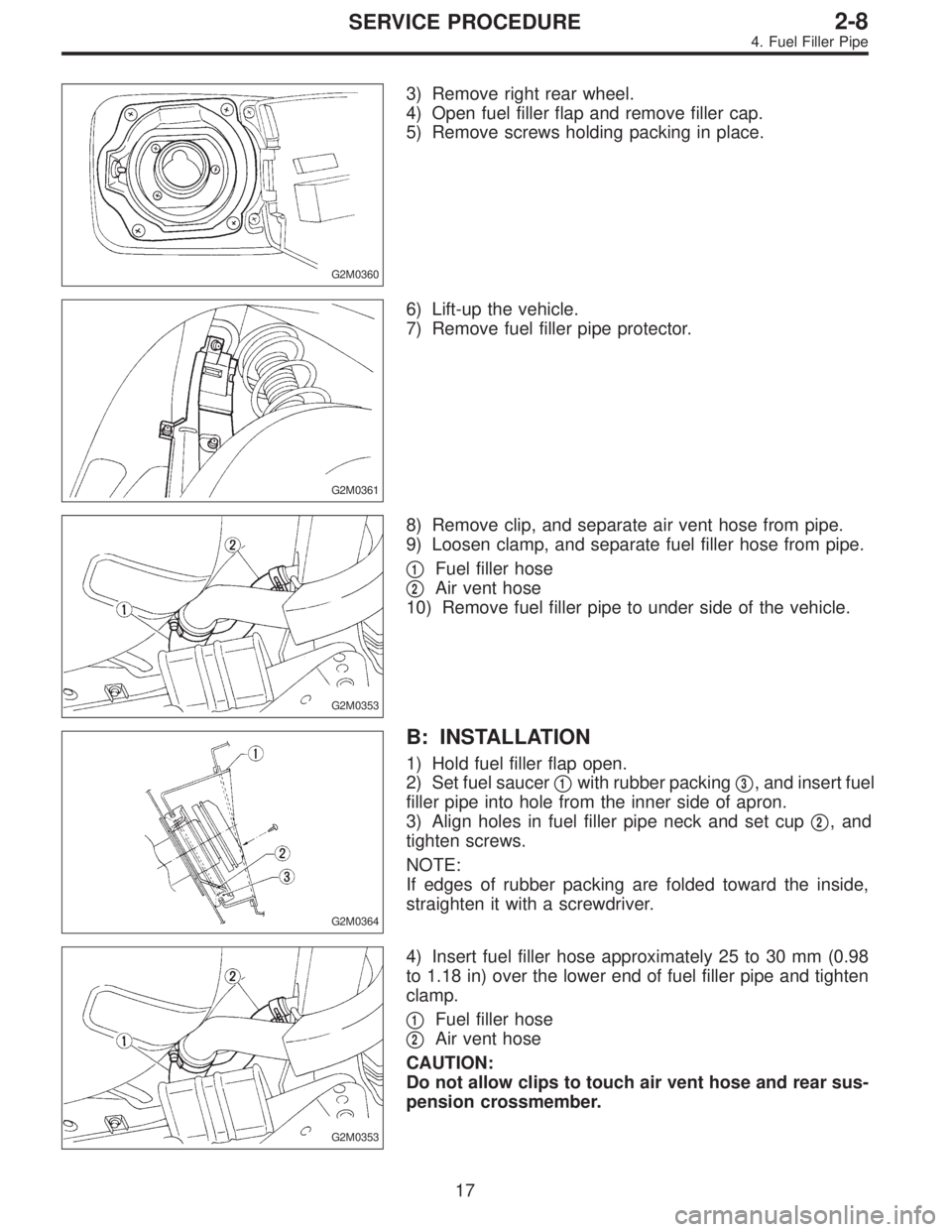
3) Remove right rear wheel.
4) Open fuel filler flap and remove filler cap.
5) Remove screws holding packing in place.
G2M0361
6) Lift-up the vehicle.
7) Remove fuel filler pipe protector.
G2M0353
8) Remove clip, and separate air vent hose from pipe.
9) Loosen clamp, and separate fuel filler hose from pipe.
�
1Fuel filler hose
�
2Air vent hose
10) Remove fuel filler pipe to under side of the vehicle.
G2M0364
B: INSTALLATION
1) Hold fuel filler flap open.
2) Set fuel saucer�
1with rubber packing�3, and insert fuel
filler pipe into hole from the inner side of apron.
3) Align holes in fuel filler pipe neck and set cup�
2, and
tighten screws.
NOTE:
If edges of rubber packing are folded toward the inside,
straighten it with a screwdriver.
G2M0353
4) Insert fuel filler hose approximately 25 to 30 mm (0.98
to 1.18 in) over the lower end of fuel filler pipe and tighten
clamp.
�
1Fuel filler hose
�
2Air vent hose
CAUTION:
Do not allow clips to touch air vent hose and rear sus-
pension crossmember.
17
2-8SERVICE PROCEDURE
4. Fuel Filler Pipe
Page 677 of 2890
G2M0358
5) Insert air vent hose approximately 25 to 30 mm (0.98 to
1.18 in) into the lower end of air vent pipe and hold clip.
�
1Hose
�
2Clip
�
3Pipe
L=25—30 mm (0.98—1.18 in)
G2M0361
6) Install fuel filler pipe protector.
7) Install right rear wheel.
5. Fuel Filter
A: REMOVAL
1) Release fuel pressure.
G2M0347
2) Disconnect fuel delivery hoses from fuel filter.
3) Remove filter from holder.
B: INSPECTION
1) Check the inside of fuel filter for dirt and water sedi-
ment.
2) If it is clogged, or if replacement interval has been
reached, replace it.
3) If water is found in it, shake and expel the water from
inlet port.
18
2-8SERVICE PROCEDURE
4. Fuel Filler Pipe - 5. Fuel Filter
Page 678 of 2890
G2M0358
5) Insert air vent hose approximately 25 to 30 mm (0.98 to
1.18 in) into the lower end of air vent pipe and hold clip.
�
1Hose
�
2Clip
�
3Pipe
L=25—30 mm (0.98—1.18 in)
G2M0361
6) Install fuel filler pipe protector.
7) Install right rear wheel.
5. Fuel Filter
A: REMOVAL
1) Release fuel pressure.
G2M0347
2) Disconnect fuel delivery hoses from fuel filter.
3) Remove filter from holder.
B: INSPECTION
1) Check the inside of fuel filter for dirt and water sedi-
ment.
2) If it is clogged, or if replacement interval has been
reached, replace it.
3) If water is found in it, shake and expel the water from
inlet port.
18
2-8SERVICE PROCEDURE
4. Fuel Filler Pipe - 5. Fuel Filter
Page 707 of 2890
B2M0633A
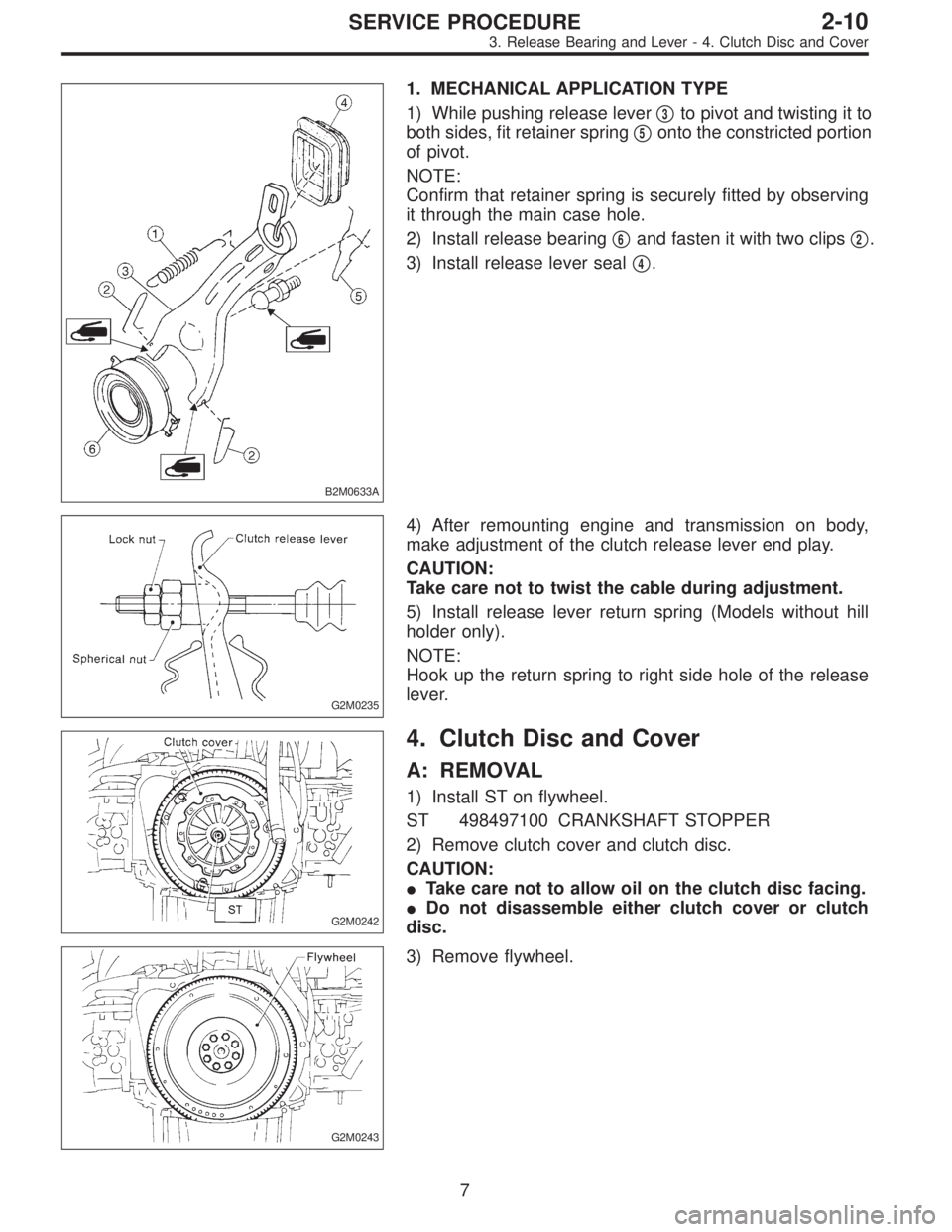
1. MECHANICAL APPLICATION TYPE
1) While pushing release lever�
3to pivot and twisting it to
both sides, fit retainer spring�
5onto the constricted portion
of pivot.
NOTE:
Confirm that retainer spring is securely fitted by observing
it through the main case hole.
2) Install release bearing�
6and fasten it with two clips�2.
3) Install release lever seal�
4.
G2M0235
4) After remounting engine and transmission on body,
make adjustment of the clutch release lever end play.
CAUTION:
Take care not to twist the cable during adjustment.
5) Install release lever return spring (Models without hill
holder only).
NOTE:
Hook up the return spring to right side hole of the release
lever.
G2M0242
4. Clutch Disc and Cover
A: REMOVAL
1) Install ST on flywheel.
ST 498497100 CRANKSHAFT STOPPER
2) Remove clutch cover and clutch disc.
CAUTION:
�Take care not to allow oil on the clutch disc facing.
�Do not disassemble either clutch cover or clutch
disc.
G2M0243
3) Remove flywheel.
7
2-10SERVICE PROCEDURE
3. Release Bearing and Lever - 4. Clutch Disc and Cover
Page 708 of 2890
B2M0633A
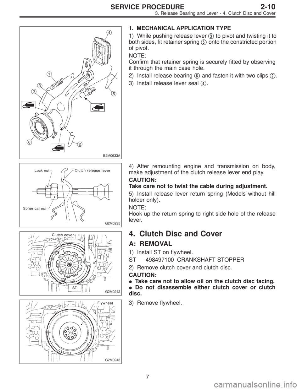
1. MECHANICAL APPLICATION TYPE
1) While pushing release lever�
3to pivot and twisting it to
both sides, fit retainer spring�
5onto the constricted portion
of pivot.
NOTE:
Confirm that retainer spring is securely fitted by observing
it through the main case hole.
2) Install release bearing�
6and fasten it with two clips�2.
3) Install release lever seal�
4.
G2M0235
4) After remounting engine and transmission on body,
make adjustment of the clutch release lever end play.
CAUTION:
Take care not to twist the cable during adjustment.
5) Install release lever return spring (Models without hill
holder only).
NOTE:
Hook up the return spring to right side hole of the release
lever.
G2M0242
4. Clutch Disc and Cover
A: REMOVAL
1) Install ST on flywheel.
ST 498497100 CRANKSHAFT STOPPER
2) Remove clutch cover and clutch disc.
CAUTION:
�Take care not to allow oil on the clutch disc facing.
�Do not disassemble either clutch cover or clutch
disc.
G2M0243
3) Remove flywheel.
7
2-10SERVICE PROCEDURE
3. Release Bearing and Lever - 4. Clutch Disc and Cover
Page 710 of 2890
G2M0248
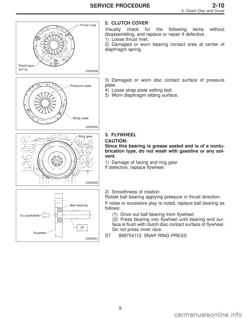
2. CLUTCH COVER
Visually check for the following items without
disassembling, and replace or repair if defective.
1) Loose thrust rivet.
2) Damaged or worn bearing contact area at center of
diaphragm spring.
G2M0249
3) Damaged or worn disc contact surface of pressure
plate.
4) Loose strap plate setting bolt.
5) Worn diaphragm sliding surface.
G2M0250
3. FLYWHEEL
CAUTION:
Since this bearing is grease sealed and is of a nonlu-
brication type, do not wash with gasoline or any sol-
vent.
1) Damage of facing and ring gear
If defective, replace flywheel.
G2M0251
2) Smoothness of rotation
Rotate ball bearing applying pressure in thrust direction.
If noise or excessive play is noted, replace ball bearing as
follows:
(1) Drive out ball bearing from flywheel.
(2) Press bearing into flywheel until bearing end sur-
face is flush with clutch disc contact surface of flywheel.
Do not press inner race.
ST 899754112 SNAP RING PRESS
9
2-10SERVICE PROCEDURE
4. Clutch Disc and Cover
Page 711 of 2890
B2M0331A
B2M0332A
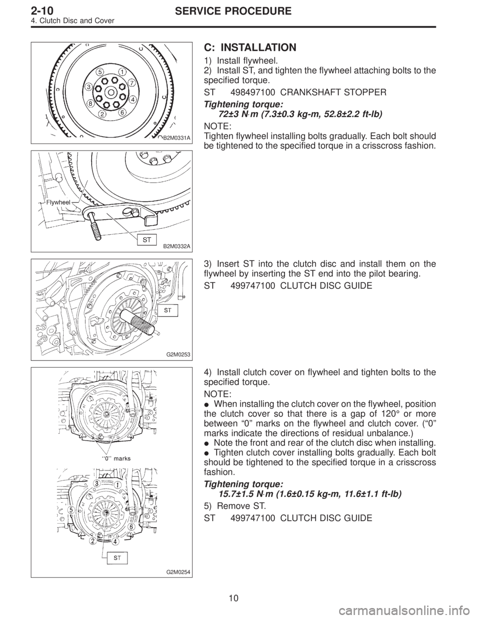
C: INSTALLATION
1) Install flywheel.
2) Install ST, and tighten the flywheel attaching bolts to the
specified torque.
ST 498497100 CRANKSHAFT STOPPER
Tightening torque:
72±3 N⋅m (7.3±0.3 kg-m, 52.8±2.2 ft-lb)
NOTE:
Tighten flywheel installing bolts gradually. Each bolt should
be tightened to the specified torque in a crisscross fashion.
G2M0253
3) Insert ST into the clutch disc and install them on the
flywheel by inserting the ST end into the pilot bearing.
ST 499747100 CLUTCH DISC GUIDE
G2M0254
4) Install clutch cover on flywheel and tighten bolts to the
specified torque.
NOTE:
�When installing the clutch cover on the flywheel, position
the clutch cover so that there is a gap of 120°or more
between“0”marks on the flywheel and clutch cover. (“0”
marks indicate the directions of residual unbalance.)
�Note the front and rear of the clutch disc when installing.
�Tighten clutch cover installing bolts gradually. Each bolt
should be tightened to the specified torque in a crisscross
fashion.
Tightening torque:
15.7±1.5 N⋅m (1.6±0.15 kg-m, 11.6±1.1 ft-lb)
5) Remove ST.
ST 499747100 CLUTCH DISC GUIDE
10
2-10SERVICE PROCEDURE
4. Clutch Disc and Cover
Page 712 of 2890
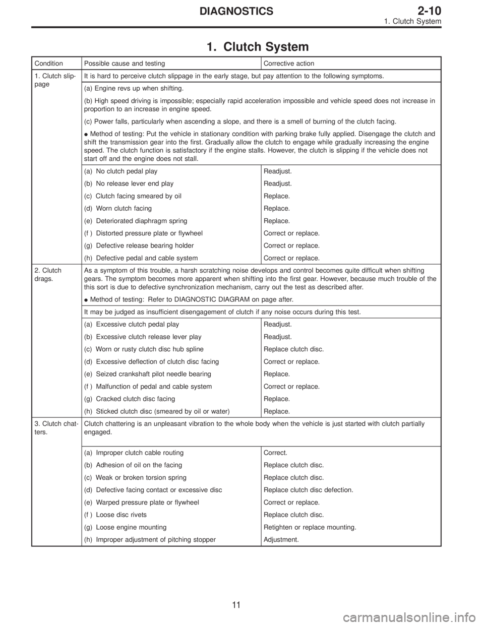
1. Clutch System
Condition Possible cause and testing Corrective action
1. Clutch slip-
pageIt is hard to perceive clutch slippage in the early stage, but pay attention to the following symptoms.
(a) Engine revs up when shifting.
(b) High speed driving is impossible; especially rapid acceleration impossible and vehicle speed does not increase in
proportion to an increase in engine speed.
(c) Power falls, particularly when ascending a slope, and there is a smell of burning of the clutch facing.
�Method of testing: Put the vehicle in stationary condition with parking brake fully applied. Disengage the clutch and
shift the transmission gear into the first. Gradually allow the clutch to engage while gradually increasing the engine
speed. The clutch function is satisfactory if the engine stalls. However, the clutch is slipping if the vehicle does not
start off and the engine does not stall.
(a) No clutch pedal play Readjust.
(b) No release lever end play Readjust.
(c) Clutch facing smeared by oil Replace.
(d) Worn clutch facing Replace.
(e) Deteriorated diaphragm spring Replace.
(f ) Distorted pressure plate or flywheel Correct or replace.
(g) Defective release bearing holder Correct or replace.
(h) Defective pedal and cable system Correct or replace.
2. Clutch
drags.As a symptom of this trouble, a harsh scratching noise develops and control becomes quite difficult when shifting
gears. The symptom becomes more apparent when shifting into the first gear. However, because much trouble of the
this sort is due to defective synchronization mechanism, carry out the test as described after.
�Method of testing: Refer to DIAGNOSTIC DIAGRAM on page after.
It may be judged as insufficient disengagement of clutch if any noise occurs during this test.
(a) Excessive clutch pedal play Readjust.
(b) Excessive clutch release lever play Readjust.
(c) Worn or rusty clutch disc hub spline Replace clutch disc.
(d) Excessive deflection of clutch disc facing Correct or replace.
(e) Seized crankshaft pilot needle bearing Replace.
(f ) Malfunction of pedal and cable system Correct or replace.
(g) Cracked clutch disc facing Replace.
(h) Sticked clutch disc (smeared by oil or water) Replace.
3. Clutch chat-
ters.Clutch chattering is an unpleasant vibration to the whole body when the vehicle is just started with clutch partially
engaged.
(a) Improper clutch cable routing Correct.
(b) Adhesion of oil on the facing Replace clutch disc.
(c) Weak or broken torsion spring Replace clutch disc.
(d) Defective facing contact or excessive disc Replace clutch disc defection.
(e) Warped pressure plate or flywheel Correct or replace.
(f ) Loose disc rivets Replace clutch disc.
(g) Loose engine mounting Retighten or replace mounting.
(h) Improper adjustment of pitching stopper Adjustment.
11
2-10DIAGNOSTICS
1. Clutch System