Page 2694 of 2890
 Conduct appearance inspection on parts selected.
: Is there anything unusual about the appear-
ance of airbag component parts?
: Replace faulty airbag component parts.
: Go to step2.
NOTE:
Also che")
3) Conduct appearance inspection on parts selected.
: Is there anything unusual about the appear-
ance of airbag component parts?
: Replace faulty airbag component parts.
: Go to step2.
NOTE:
Also check connector terminals, wiring harness, case, etc.
for damage.
2. AIRBAG COMPONENT PARTS VIBRATION
INSPECTION
1) Gently shake check parts (to determine faults.).
2) To check airbag module or roll connector, turn and tilt
steering wheel.
CAUTION:
Do not shake or vibrate airbag control module.
: Does the component malfunction again
when shaking?
: Replace faulty airbag component parts.
: Go to step3.
G5M0461
3. SHOWERING INSPECTION TO BODY
Spray water on vehicle body.
CAUTION:
Do not directly spray water on airbag components.
: Does water leak into the passenger com-
partment when showering vehicle?
: Replace faulty airbag component parts.
: Clear memory.
NOTE:
Also check wiring harnesses as water may leak along them
and get airbag component parts wet.
40
5-5bSUPPLEMENTAL RESTRAINT SYSTEM (ELECTRIC SENSOR TYPE)
5. Diagnostics Chart with Trouble Code
Page 2695 of 2890

Q: WARNING LIGHT INDICATES TROUBLE
CODE, THEN NORMAL CODE.
—FLASHING NORMAL CODE.—
DIAGNOSIS:
�Airbag connector is faulty.
�Fuse No. 16 is blown.
�Airbag main harness is faulty.
�Airbag control module is faulty.
�Body harness is faulty.
1. Airbag connector appearance inspection
2. Airbag connector vibration inspection
3. Showering inspection to body
4. Fuse No. 16, airbag main harness, airbag
control module, body harness appearance
inspection
5. Fuse No. 16, airbag main harness, body
harness vibration inspection
6. Showering inspection to body
7. Warning light illumination check
CAUTION:
Before performing diagnostics on airbag system, turn
ignition switch“OFF”, disconnect battery ground
cable, and then wait at least 20 seconds.
1. AIRBAG CONNECTOR APPEARANCE INSPECTION
Conduct appearance inspection on airbag connectors
(AB2) through (AB8).
: Is there anything unusual about the appear-
ance of connectors (AB2) through (AB8)?
: Replace faulty airbag component parts.
: Go to step2.
NOTE:
Check terminals, case and wiring harnesses for damage.
�
�
�
�
�
�
41
5-5bSUPPLEMENTAL RESTRAINT SYSTEM (ELECTRIC SENSOR TYPE)
5. Diagnostics Chart with Trouble Code
Page 2696 of 2890
![SUBARU LEGACY 1996 Service Repair Manual 2. AIRBAG CONNECTOR VIBRATION INSPECTION
Conduct vibration inspection on airbag connectors (AB2)
through (AB8). <Ref. to 5-5b [T100].>
: Do the connectors (AB2) through (AB8) mal-
function again when](/manual-img/17/57433/w960_57433-2695.png "SUBARU LEGACY 1996 Service Repair Manual 2. AIRBAG CONNECTOR VIBRATION INSPECTION
Conduct vibration inspection on airbag connectors (AB2)
through (AB8). <Ref. to 5-5b [T100].>
: Do the connectors (AB2) through (AB8) mal-
function again when")
2. AIRBAG CONNECTOR VIBRATION INSPECTION
Conduct vibration inspection on airbag connectors (AB2)
through (AB8).
: Do the connectors (AB2) through (AB8) mal-
function again when shaking?
: Replace faulty airbag component parts.
: Go to step3.
NOTE:
Gently shake each airbag connector.
G5M0461
3. SHOWERING INSPECTION TO BODY
Spray water on vehicle body.
CAUTION:
Do not directly spray water on airbag components.
: Does water leak into the passenger com-
partment when showering vehicle?
: Replace faulty airbag component parts.
: Go to step4.
NOTE:
If leaks are noted, also check wiring harnesses as water
may leak along them and wet airbag connectors.
4. FUSE No. 16, AIRBAG MAIN HARNESS, AIRBAG
CONTROL MODULE, BODY HARNESS APPEARANCE
INSPECTION
Conduct appearance inspection on fuse No. 16
5-5b [T5H3].>, airbag main harness
[W4A0].>, airbag control module
and body harness.
: Is there anything unusual about the appear-
ance of fuse No. 16, airbag main harness,
airbag control module or body harness?
: Replace faulty airbag component parts.
: Go to step5.
NOTE:
Also check connectors, terminals, wiring harness and case
for damage.
42
5-5bSUPPLEMENTAL RESTRAINT SYSTEM (ELECTRIC SENSOR TYPE)
5. Diagnostics Chart with Trouble Code
Page 2697 of 2890

5. FUSE No. 16, AIRBAG MAIN HARNESS, BODY
HARNESS VIBRATION INSPECTION
Conduct vibration inspection on fuse No. 16, airbag main
harness and body harness.
CAUTION:
Do not shake or vibrate airbag control module.
: Do fuse No. 16, airbag main harness or
body harness malfunction again when shak-
ing?
: Replace faulty airbag component parts.
: Go to step6.
NOTE:
Gently shake each part.
G5M0461
6. SHOWERING INSPECTION TO BODY
Spray water on vehicle body.
CAUTION:
Do not directly spray water on each part.
: Does water leak into the passenger com-
partment when showering vehicle?
: Replace faulty airbag component parts.
: Go to step7.
NOTE:
If leaks are noted, check wiring harnesses as water may
leak along them and get parts wet.
7. WARNING LIGHT ILLUMINATION CHECK
Turn ignition switch“ON”(engine off) and observe airbag
warning light.
: Does the airbag warning light comes on for
8 seconds, then go out and stay out?
: Clear memory.
: Go to 5-5b [T4E0]“DIAGNOSTICS PROCE-
DURE”.
43
5-5bSUPPLEMENTAL RESTRAINT SYSTEM (ELECTRIC SENSOR TYPE)
5. Diagnostics Chart with Trouble Code
Page 2698 of 2890

1. Supplemental Restraint System
“Airbag”
Airbag system wiring harness is routed near the cruise
control command switch.
CAUTION:
�All Airbag system wiring harness and connectors
are colored yellow. Do not use electrical test equip-
ment on these circuits.
�Be careful not to damage Airbag system wiring har-
ness when servicing the cruise control command
switch.
B6M0171A
B6M0241A
2. Pre-inspection
1. CRUISE CONTROL CABLE
1) Cable installation
(1) Ensure that cruise control cable is attached to the left
of accelerator cable (on accelerator pedal side).
(2) Ensure that accelerator cable throttle cam does not
move when cruise control throttle cam is moved by hand.
(3) Ensure that throttle cam moves smoothly.
2) Cable free play
(1) Ensure that throttle cam-to-lever clearance is within
specifications.
Standard value: 1
0
�1mm (0.040
�0.04in)
NOTE:
If clearance is not within specifications, adjust cable at its
outer end.
(2) Ensure that cap is positioned in groove.
2
6-2BODY ELECTRICAL SYSTEM
1. Supplemental Restraint System“Airbag”- 2. Pre-inspection
Page 2699 of 2890

1. Supplemental Restraint System
“Airbag”
Airbag system wiring harness is routed near the cruise
control command switch.
CAUTION:
�All Airbag system wiring harness and connectors
are colored yellow. Do not use electrical test equip-
ment on these circuits.
�Be careful not to damage Airbag system wiring har-
ness when servicing the cruise control command
switch.
B6M0171A
B6M0241A
2. Pre-inspection
1. CRUISE CONTROL CABLE
1) Cable installation
(1) Ensure that cruise control cable is attached to the left
of accelerator cable (on accelerator pedal side).
(2) Ensure that accelerator cable throttle cam does not
move when cruise control throttle cam is moved by hand.
(3) Ensure that throttle cam moves smoothly.
2) Cable free play
(1) Ensure that throttle cam-to-lever clearance is within
specifications.
Standard value: 1
0
�1mm (0.040
�0.04in)
NOTE:
If clearance is not within specifications, adjust cable at its
outer end.
(2) Ensure that cap is positioned in groove.
2
6-2BODY ELECTRICAL SYSTEM
1. Supplemental Restraint System“Airbag”- 2. Pre-inspection
Page 2709 of 2890
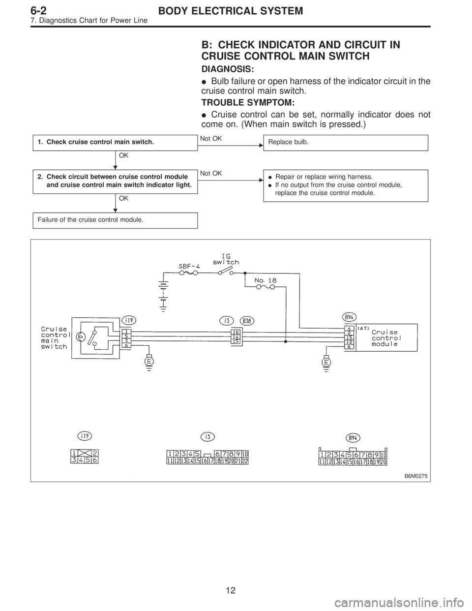
B: CHECK INDICATOR AND CIRCUIT IN
CRUISE CONTROL MAIN SWITCH
DIAGNOSIS:
�Bulb failure or open harness of the indicator circuit in the
cruise control main switch.
TROUBLE SYMPTOM:
�Cruise control can be set, normally indicator does not
come on. (When main switch is pressed.)
1. Check cruise control main switch.
OK
�Not OK
Replace bulb.
2. Check circuit between cruise control module
and cruise control main switch indicator light.
OK
�Not OK
�Repair or replace wiring harness.
�If no output from the cruise control module,
replace the cruise control module.
Failure of the cruise control module.
B6M0275
�
�
12
6-2BODY ELECTRICAL SYSTEM
7. Diagnostics Chart for Power Line
Page 2711 of 2890
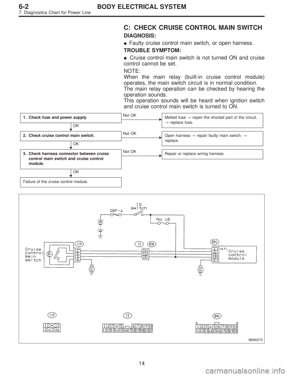
C: CHECK CRUISE CONTROL MAIN SWITCH
DIAGNOSIS:
�Faulty cruise control main switch, or open harness.
TROUBLE SYMPTOM:
�Cruise control main switch is not turned ON and cruise
control cannot be set.
NOTE:
When the main relay (built-in cruise control module)
operates, the main switch circuit is in normal condition.
The main relay operation can be checked by hearing the
operation sounds.
This operation sounds will be heard when ignition switch
and cruise control main switch is turned to ON.
1. Check fuse and power supply.
OK
�Not OK
Melted fuse,repair the shorted part of the circuit.
,replace fuse.
2. Check cruise control main switch.
OK
�Not OK
Open harness,repair faulty main switch.,
replace.
3. Check harness connector between cruise
control main switch and cruise control
module.
OK
�Not OK
Repair or replace wiring harness.
Failure of the cruise control module.
B6M0275
�
�
�
14
6-2BODY ELECTRICAL SYSTEM
7. Diagnostics Chart for Power Line