Page 2714 of 2890
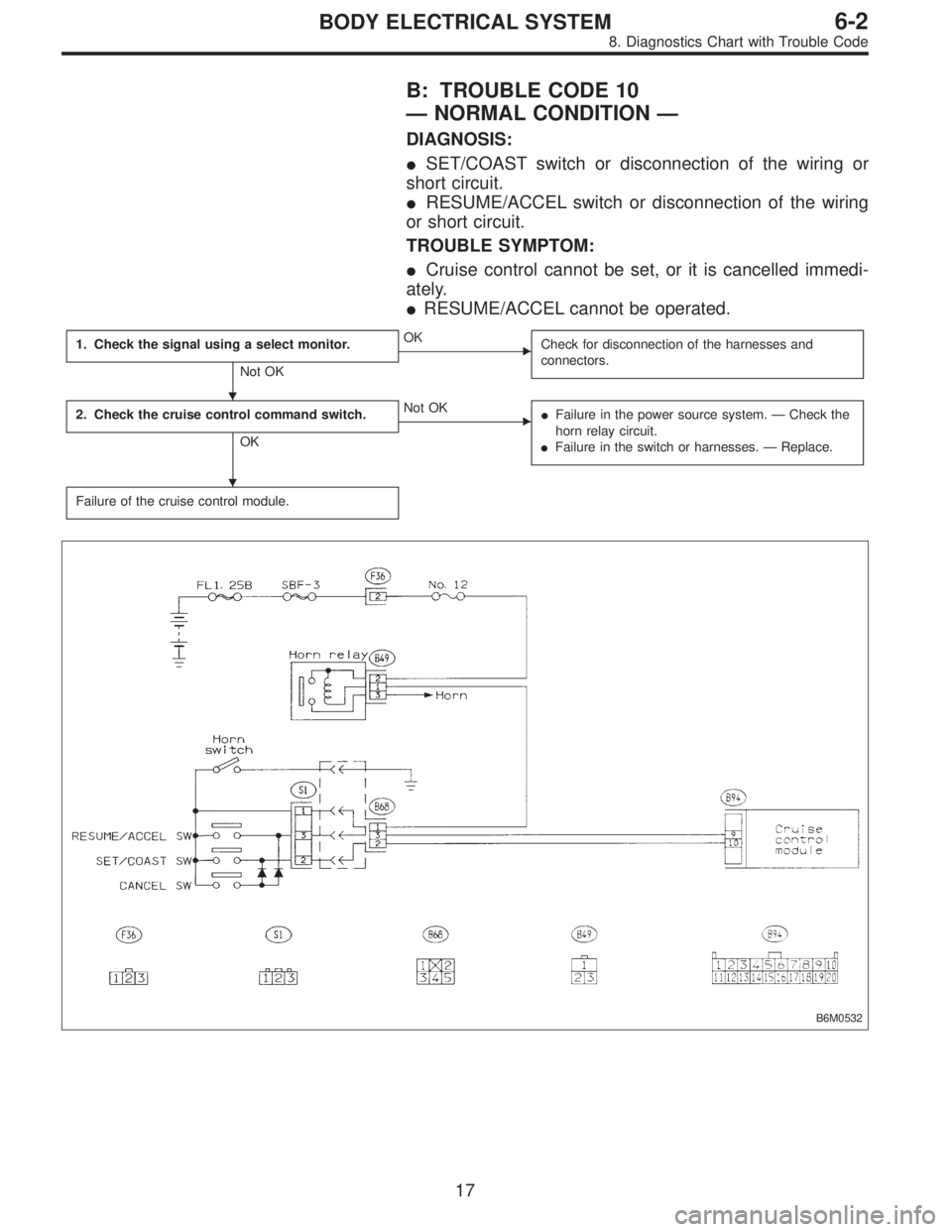
B: TROUBLE CODE 10
—NORMAL CONDITION—
DIAGNOSIS:
�SET/COAST switch or disconnection of the wiring or
short circuit.
�RESUME/ACCEL switch or disconnection of the wiring
or short circuit.
TROUBLE SYMPTOM:
�Cruise control cannot be set, or it is cancelled immedi-
ately.
�RESUME/ACCEL cannot be operated.
1. Check the signal using a select monitor.
Not OK
�OK
Check for disconnection of the harnesses and
connectors.
2. Check the cruise control command switch.
OK
�Not OK
�Failure in the power source system.—Check the
horn relay circuit.
�Failure in the switch or harnesses.—Replace.
Failure of the cruise control module.
B6M0532
�
�
17
6-2BODY ELECTRICAL SYSTEM
8. Diagnostics Chart with Trouble Code
Page 2716 of 2890
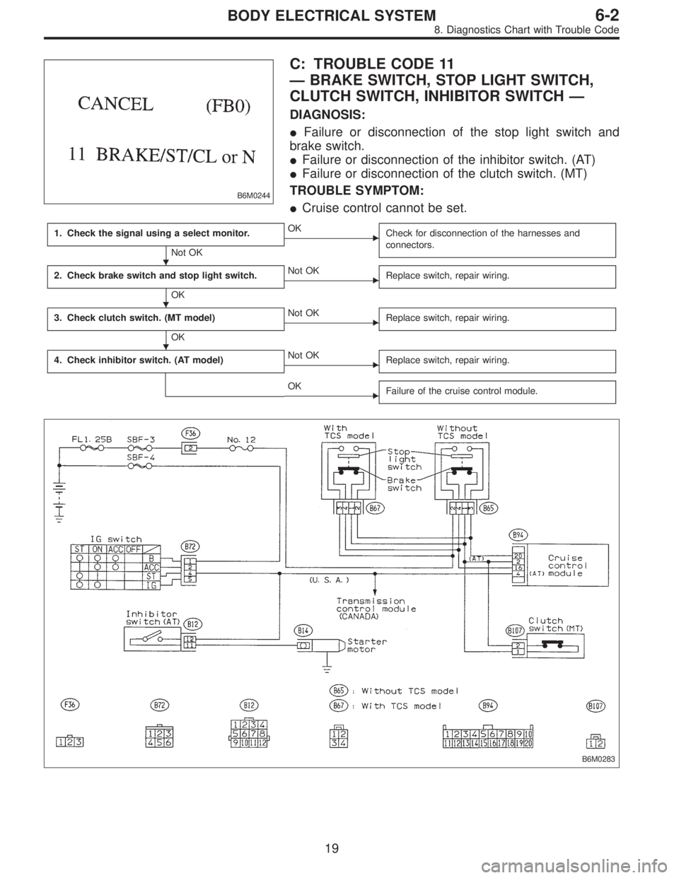
B6M0244
C: TROUBLE CODE 11
—BRAKE SWITCH, STOP LIGHT SWITCH,
CLUTCH SWITCH, INHIBITOR SWITCH—
DIAGNOSIS:
�Failure or disconnection of the stop light switch and
brake switch.
�Failure or disconnection of the inhibitor switch. (AT)
�Failure or disconnection of the clutch switch. (MT)
TROUBLE SYMPTOM:
�Cruise control cannot be set.
1. Check the signal using a select monitor.
Not OK
�OK
Check for disconnection of the harnesses and
connectors.
2. Check brake switch and stop light switch.
OK
�Not OK
Replace switch, repair wiring.
3. Check clutch switch. (MT model)
OK
�Not OK
Replace switch, repair wiring.
4. Check inhibitor switch. (AT model)�Not OK
Replace switch, repair wiring.
�OK
Failure of the cruise control module.
B6M0283
�
�
�
19
6-2BODY ELECTRICAL SYSTEM
8. Diagnostics Chart with Trouble Code
Page 2726 of 2890
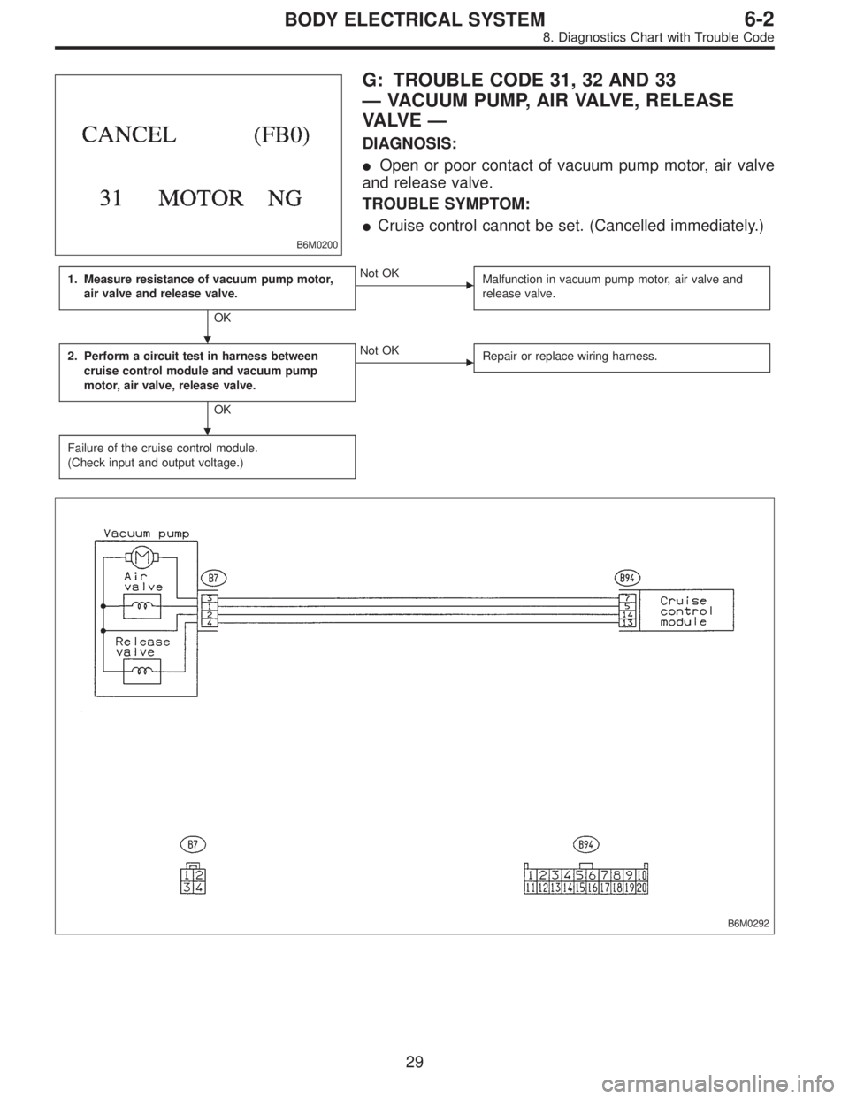
B6M0200
G: TROUBLE CODE 31, 32 AND 33
—VACUUM PUMP, AIR VALVE, RELEASE
VA LV E—
DIAGNOSIS:
�Open or poor contact of vacuum pump motor, air valve
and release valve.
TROUBLE SYMPTOM:
�Cruise control cannot be set. (Cancelled immediately.)
1. Measure resistance of vacuum pump motor,
air valve and release valve.
OK
�Not OK
Malfunction in vacuum pump motor, air valve and
release valve.
2. Perform a circuit test in harness between
cruise control module and vacuum pump
motor, air valve, release valve.
OK
�Not OK
Repair or replace wiring harness.
Failure of the cruise control module.
(Check input and output voltage.)
B6M0292
�
�
29
6-2BODY ELECTRICAL SYSTEM
8. Diagnostics Chart with Trouble Code
Page 2732 of 2890
1. General Description
1. HOW TO USE THIS MANUAL
The description of the electrical system is divided into the
charging system, starting system, etc.
1) First, open to the necessary electrical system section
and wiring diagram.
2) Next, open the foldout page of the electrical wiring dia-
gram. By observing the electrical wiring harness’ illustra-
tions (front, instrument panel, etc.), the wiring diagram con-
nector can be located.
G6M0192
G6M0193
2. WIRING DIAGRAM
The wiring diagram of each system is illustrated so that you
can understand the path through which the electric current
flows from the battery.
Sketches and codes are used in the diagrams. They should
read as follows:
1) Each connector and its terminal position are indicated
by a sketch of the connector in a disconnected state which
is viewed from the front, as shown in figure.
2
6-3WIRING DIAGRAM
1. General Description
Page 2733 of 2890
 The number of poles or pins, presence of a lock, and pin
number of each terminal are indicated in the sketch of each
connector.
In the sketch, the highest pole number refers to the num-
ber of pole")
2) The number of poles or pins, presence of a lock, and pin
number of each terminal are indicated in the sketch of each
connector.
In the sketch, the highest pole number refers to the num-
ber of poles which the connector has. For example, the
sketch of the connector shown in figure indicates the con-
nector has 9 poles.
Connector used in vehicleConnector shown in wiring diagram
Sketch Symbol Number of poles
G6M0194G6M0196
G6M0198
Numbered in order from
upper right to lower left.
G6M0195G6M0197
Numbered in order from
upper left to lower right.
G6M0199
When one set of connectors is viewed from the front side,
the pole numbers of one connector are symmetrical to
those of the other. When these two connectors are con-
nected as a unit, the poles which have the same number
are joined.
3) Electrical wiring harness
The connectors are numbered along with the number of
poles, external colors, and mating connections in the
accompanying list.
3
6-3WIRING DIAGRAM
1. General Description
Page 2734 of 2890
 The sketch of each connector in the wiring diagram
usually shows the“A”side of the connector. The relation-
ship between the wire color, terminal number and connec-
tor is described in")
G6M0200
4) The sketch of each connector in the wiring diagram
usually shows the“A”side of the connector. The relation-
ship between the wire color, terminal number and connec-
tor is described in figure.
NOTE:
A wire which runs in one direction from a connector termi-
nal sometimes may have a different color from that which
runs in the other direction from that terminal.
G6M0216
5) In wiring diagram, connectors which have no terminal
number refer to one-pole types. Sketches of these connec-
tors are omitted intentionally.
G6M0201
6) The following color codes are used to indicate the col-
ors of the wires used.
Color code Color
L Blue
B Black
Y Yellow
G Green
RRed
W White
Br Brown
Lg Light green
Gr Gray
P Pink
Or Orange
Lb Light Blue
V Violet
SA Sealed (Inner)
SB Sealed (Outer)
G6M0202
7) The wire color code, which consists of two letters (or
three letters including Br or Lg), indicates the standard
color (base color of the wire covering) by its first letter and
the stripe marking by its second letter.
4
6-3WIRING DIAGRAM
1. General Description
Page 2735 of 2890
 The table below lists the nominal sectional areas and
allowable currents of the wires.
Nominal
sectional area
mm
2
No. of strands/
strand diameterOutside
diameter of
finished wiring
mmAllowable
cur")
8) The table below lists the nominal sectional areas and
allowable currents of the wires.
Nominal
sectional area
mm
2
No. of strands/
strand diameterOutside
diameter of
finished wiring
mmAllowable
current
Amps/40°C
0.3 7/0.26 1.8 7
0.5 7/0.32 2.2 (or 2.0) 12
0.75 30/0.18 2.6 (or 2.4) 16
0.85 11/0.32 2.4 (or 2.2) 16
1.25 16/0.32 2.7 (or 2.5) 21
2 26/0.32 3.1 (or 2.9) 28
3 41/0.32 3.8 (or 3.6) 38
5 65/0.32 4.6 (or 4.4) 51
8 50/0.45 5.5 67
CAUTION:
When replacing or repairing a wire, be sure to use the
same size and type of the wire which was originally
used.
NOTE:
�The allowable current in the above table indicates the
tolerable amperage of each wire at an ambient tempera-
ture of 40°C (104°F).
�The allowable current changes with ambient tempera-
ture. Also, it changes if a bundle of more than two wires is
used.
G6M0203
9) Each unit is directly grounded to the body or indirectly
grounds through a harness ground terminal. Different sym-
bols are used in the wiring diagram to identify the two
grounding systems.
The ground points shown in the wiring diagram refer to the
following:
�GBBody ground
�GEEngine ground
�GRRadio ground
�GDRear defogger ground
All wiring harnesses are provided with a ground point which
should be securely connected.
5
6-3WIRING DIAGRAM
1. General Description
Page 2736 of 2890
10) Relays are classified as normally-open or normally-
closed.
The normally-closed relay has one or more contacts.
The wiring diagram shows the relay mode when the ener-
gizing circuit is OFF.
G6M0204
Key to symbols:
�→: Current flows.
X→: Current does not flow.
6
6-3WIRING DIAGRAM
1. General Description
 First, open to the necessary electrical system s")
 Relays are classified as normally-open or normally-
closed.
The normally-closed relay has one or more contacts.
The wiring diagram shows the relay mode when the ener-
gizing circuit is OFF.
G6M020")