Page 2600 of 2890
B4M0982
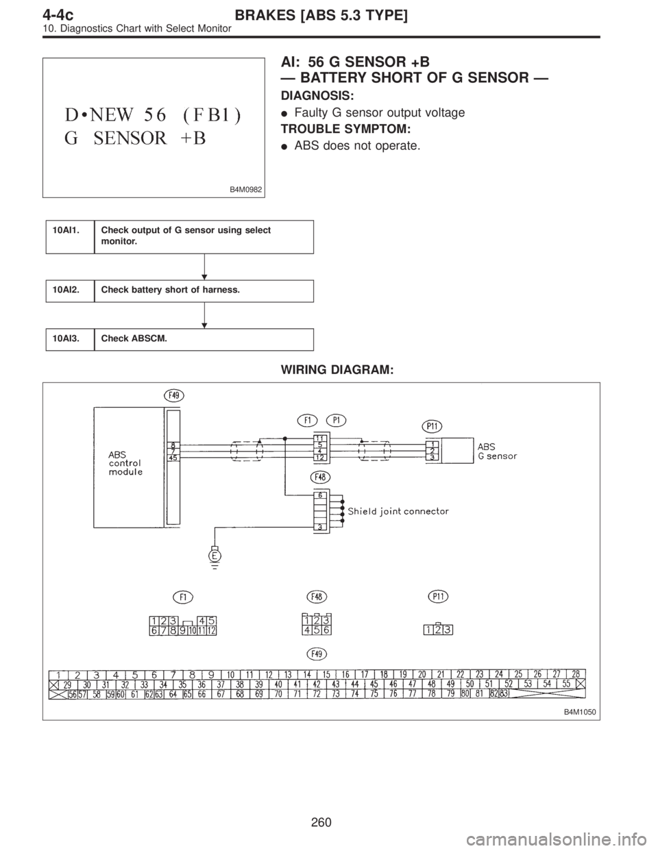
AI: 56 G SENSOR +B
—BATTERY SHORT OF G SENSOR—
DIAGNOSIS:
�Faulty G sensor output voltage
TROUBLE SYMPTOM:
�ABS does not operate.
10AI1.Check output of G sensor using select
monitor.
10AI2.Check battery short of harness.
10AI3.Check ABSCM.
WIRING DIAGRAM:
B4M1050
�
�
260
4-4cBRAKES [ABS 5.3 TYPE]
10. Diagnostics Chart with Select Monitor
Page 2603 of 2890
WIRING DIAGRAM:
B4M1050
B4M0927
10AJ1CHECK OUTPUT OF G SENSOR USING
SELECT MONITOR.
1) Press F,1and 0on the select monitor.
2) Read the select monitor display.
: Is the indicated reading 2.3±0.2 V when the
G sensor is in horizontal position?
: Go to step10AJ2.
: Go to step10AJ5.
10AJ2CHECK POOR CONTACT IN CONNEC-
TOR BETWEEN ABSCM AND G SENSOR.
: Is there poor contact in connector between
ABSCM and G sensor?
: Repair connector.
: Go to step10AJ3.
263
4-4cBRAKES [ABS 5.3 TYPE]
10. Diagnostics Chart with Select Monitor
Page 2607 of 2890
WIRING DIAGRAM:
B4M1050
10AK1CHECK ALL FOUR WHEELS FOR FREE
TURNING.
: Have the wheels been turned freely such as
when the vehicle is lifted up, or operated on
a rolling road?
: The ABS is normal. Erase the trouble code.
: Go to step10AK2.
B4M0927
10AK2CHECK OUTPUT OF G SENSOR USING
SELECT MONITOR.
1) Press F,1and 0on the select monitor.
2) Read the select monitor display.
: Is the indicated reading 2.3±0.2 V when the
vehicle is in horizontal position?
: Go to next step.
: Go to step10AK5.
267
4-4cBRAKES [ABS 5.3 TYPE]
10. Diagnostics Chart with Select Monitor
Page 2612 of 2890

�ABS s")
11. General Diagnostics Table
A: SYMPTOMS AND PROBABLE CAUSES
Symptom Probable faulty units/parts
Vehicle instability during brakingVehicle pulls to either side.�Hydraulic unit (solenoid valve)
�ABS sensor
�Brake (caliper & piston, pads)
�Wheel alignment
�Tire specifications, tire wear and air pressures
�Incorrect wiring or piping connections
�Road surface (uneven, camber)
Vehicle spins.�Hydraulic unit (solenoid valve)
�ABS sensor
�Brake (pads)
�Tire specifications, tire wear and air pressures
�Incorrect wiring or piping connections
Poor brakingLong braking/stopping distance�Hydraulic unit (solenoid valve)
�Brake (pads)
�Air in brake line
�Tire specifications, tire wear and air pressures
�Incorrect wiring or piping connections
Wheel locks.�Hydraulic unit (solenoid valve, motor)
�ABS sensor
�Incorrect wiring or piping connections
Brake dragging�Hydraulic unit (solenoid valve)
�ABS sensor
�Master cylinder
�Brake (caliper & piston)
�Parking brake
�Axle & wheels
�Brake pedal play
Long brake pedal stroke�Air in brake line
�Brake pedal play
Vehicle pitching�Suspension play or fatigue (reduced damping)
�Incorrect wiring or piping connections
�Road surface (uneven)
Unstable or uneven braking�Hydraulic unit (solenoid valve)
�ABS sensor
�Brake (caliper & piston, pads)
�Tire specifications, tire wear and air pressures
�Incorrect wiring or piping connections
�Road surface (uneven)
Vibration and/or noise (while
driving on slippery roads)Excessive pedal vibration�Incorrect wiring or piping connections
�Road surface (uneven)
Noise from hydraulic unit�Hydraulic unit (mount bushing)
�ABS sensor
�Brake piping
Noise from front of vehicle�Hydraulic unit (mount bushing)
�ABS sensor
�Master cylinder
�Brake (caliper & piston, pads, rotor)
�Brake piping
�Brake booster & check valve
�Suspension play or fatigue
Noise from rear of vehicle�ABS sensor
�Brake (caliper & piston, pads, rotor)
�Parking brake
�Brake piping
�Suspension play or fatigue
272
4-4cBRAKES [ABS 5.3 TYPE]
11. General Diagnostics Table
Page 2613 of 2890
B: CHECKING THE HYDRAULIC UNIT
OPERATION
1) Do ABS sequence control patterns take place in correct
order?
If not, check wiring and piping for incorrect connections.
2) Are oil pressure or braking force variations within speci-
fications?
If not, check master cylinder, brake piping, hydraulic unit,
proportioning valve and wheel cylinder for improper opera-
tion.
3) Does pedal hardness change before and after ABS
sequence control?
If so, bleed air from brake line.
273
4-4cBRAKES [ABS 5.3 TYPE]
11. General Diagnostics Table
Page 2653 of 2890
2. AIRBAG COMPONENT PARTS APPEARANCE
INSPECTION
Conduct appearance inspection on parts selected.
NOTE:
Also check connector terminals, wiring harness, case, etc.
for damage.
3. AIRBAG COMPONENT PARTS VIBRATION
INSPECTION
1) Gently shake check parts (to determine faults.).
2) To check airbag module or roll connector, turn and tilt
steering wheel.
CAUTION:
Do not shake or vibrate airbag control module and
front sensor at the same time as erroneous operation
may result.
G5M0461
4. SHOWERING INSPECTION TO BODY
1) Spray water on vehicle body.
CAUTION:
Do not directly spray water on airbag components.
2) Check passenger compartment for traces of leaking.
NOTE:
Also check wiring harnesses as water may leak along them
and get airbag component parts wet.
42
5-5SUPPLEMENTAL RESTRAINT SYSTEM
5. Diagnostics Chart with Trouble Code
Page 2654 of 2890

Q: WARNING LIGHT INDICATES TROUBLE
CODE, THEN NORMAL CODE.
—FLASHING NORMAL CODE.—
DIAGNOSIS:
�Airbag connector is faulty.
�Fuse No. 16 is blown.
�Airbag main harness is faulty.
�Airbag control module is faulty.
�Body harness is faulty.
1. Airbag connectors appearance and vibration
inspection
O.K.
�Not O.K.
Replace faulty parts.
2. Showering inspection to body
O.K.
�Not O.K.
Replace faulty parts.
3. Fuse No. 16, airbag main harness, airbag
control module, body harness appearance and
vibration inspection
O.K.
�Not O.K.
Replace faulty parts.
4. Showering inspection to body
O.K.
�Not O.K.
Replace faulty parts.
5. Warning light illumination check
O.K.
�Not O.K.
Go to“T4E0”diagnostics procedure.
Clear memory.
CAUTION:
Before performing diagnostics on airbag system, turn
ignition switch“OFF”, disconnect battery ground
cable, and then wait at least 20 seconds.
1. AIRBAG CONNECTORS APPEARANCE AND
VIBRATION INSPECTION
1) Conduct appearance inspection on airbag connectors
(AB2 through AB8).
NOTE:
Check terminals, case and wiring harnesses for damage.
2) Conduct vibration inspection on airbag connectors (AB2
through AB8).
NOTE:
Gently shake each airbag connector.
�
�
�
�
�
43
5-5SUPPLEMENTAL RESTRAINT SYSTEM
5. Diagnostics Chart with Trouble Code
Page 2655 of 2890
 Spray water on vehicle body.
CAUTION:
Do not directly spray water on airbag components.
2) Check passenger compartment for traces of leaking.
NOTE:
If leaks")
G5M0461
2. SHOWERING INSPECTION TO BODY
1) Spray water on vehicle body.
CAUTION:
Do not directly spray water on airbag components.
2) Check passenger compartment for traces of leaking.
NOTE:
If leaks are noted, also check wiring harnesses as water
may leak along them and wet airbag connectors.
3. FUSE No. 16, AIRBAG MAIN HARNESS, AIRBAG
CONTROL MODULE, BODY HARNESS APPEARANCE
AND VIBRATION INSPECTION
1) Conduct appearance inspection on fuse No. 16
5-5 [T5L3].>, airbag main harness ,
airbag control module and body
harness.
NOTE:
Also check connectors, terminals, wiring harness and case
for damage.
2) Conduct vibration inspection on fuse No. 16, airbag
main harness, airbag control module and body harness.
NOTE:
Gently shake each part.
G5M0461
4. SHOWERING INSPECTION TO BODY
1) Spray water on vehicle body.
CAUTION:
Do not directly spray water on each part.
2) Check passenger compartment for traces of leaking.
NOTE:
If leaks are noted, check wiring harnesses as water may
leak along them and get parts wet.
5. WARNING LIGHT ILLUMINATION CHECK
Turn ignition switch“ON”(engine off) and observe airbag
warning light.
Airbag warning light comes“ON”for 8 seconds then goes
out and stays out.
44
5-5SUPPLEMENTAL RESTRAINT SYSTEM
5. Diagnostics Chart with Trouble Code
 Press F,1and 0on the select monitor.
2) Read the select monitor display.
: Is the indicated reading 2.3±0.2 V wh")

![SUBARU LEGACY 1996 Service Repair Manual B: CHECKING THE HYDRAULIC UNIT
OPERATION
<Ref. to 4-4 [W22C1] or [W22C2].>
1) Do ABS sequence control patterns take place in correct
order?
If not, check wiring and piping for incorrect connections.
2](/manual-img/17/57433/w960_57433-2612.png "SUBARU LEGACY 1996 Service Repair Manual B: CHECKING THE HYDRAULIC UNIT
OPERATION
<Ref. to 4-4 [W22C1] or [W22C2].>
1) Do ABS sequence control patterns take place in correct
order?
If not, check wiring and piping for incorrect connections.
2")
