Page 2527 of 2890
B4M0430
10W1
CHECK GENERATOR.
1) Start engine.
2) Idling after warm-up.
3) Measure voltage between generator B terminal and
chassis ground.
: Terminal
Generator B terminal—Chassis ground
Is voltage 10—15 V?
: Go to step10W2.
: Repair generator.
10W2
CHECK BATTERY TERMINAL.
Turn ignition switch to OFF.
: Are the positive and negative battery termi-
nals tightly clamped?
: Go to step10W3.
: Tighten the clamp of terminal.
B4M0842A
10W3
CHECK INPUT VOLTAGE OF ABSCM.
1) Disconnect connector from ABSCM.
2) Run the engine at idle.
3) Measure voltage between ABSCM connector and chas-
sis ground.
: Connector & terminal
(F49) No. 28 (+)—Chassis ground (�)
Is voltage 10—15 V?
: Go to step10W4.
: Repair harness connector between battery, igni-
tion switch and ABSCM.
187
4-4cBRAKES [ABS 5.3 TYPE]
10. Diagnostics Chart with Select Monitor
Page 2528 of 2890
B4M0843A
10W4
CHECK GROUND CIRCUIT OF ABSCM.
1) Turn ignition switch to OFF.
2) Measure resistance between ABSCM connector and
chassis ground.
: Connector & terminal
(F49) No. 1—Chassis ground
Is resistance less than 0.5Ω?
: Go to step10W5.
: Repair ABSCM ground harness.
10W5CHECK POOR CONTACT IN CONNEC-
TOR BETWEEN GENERATOR, BATTERY
AND ABSCM.
: Is there poor contact in connectors between
generator, battery and ABSCM?
: Repair connector.
: Go to step10W6.
10W6
CHECK ABSCM.
1) Connect all connectors.
2) Erase the memory.
3) Perform inspection mode.
4) Read out the trouble code.
: Is the same trouble code as in the current
diagnosis still being output?
: Replace ABSCM.
: Go to next.
: Are other trouble codes being output?
: Proceed with the diagnosis corresponding to the
trouble code.
: A temporary poor contact.
188
4-4cBRAKES [ABS 5.3 TYPE]
10. Diagnostics Chart with Select Monitor
Page 2529 of 2890
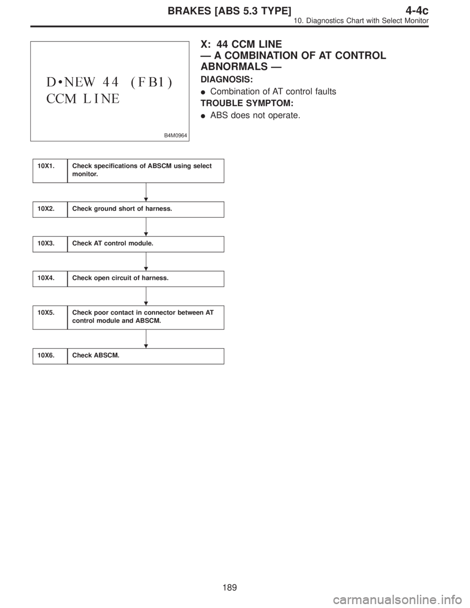
B4M0964
X: 44 CCM LINE
—A COMBINATION OF AT CONTROL
ABNORMALS—
DIAGNOSIS:
�Combination of AT control faults
TROUBLE SYMPTOM:
�ABS does not operate.
10X1.Check specifications of ABSCM using select
monitor.
10X2.Check ground short of harness.
10X3.Check AT control module.
10X4.Check open circuit of harness.
10X5.Check poor contact in connector between AT
control module and ABSCM.
10X6.Check ABSCM.
�
�
�
�
�
189
4-4cBRAKES [ABS 5.3 TYPE]
10. Diagnostics Chart with Select Monitor
Page 2530 of 2890
WIRING DIAGRAM:
B4M1040
B4M0921
10X1CHECK SPECIFICATIONS OF ABSCM
USING SELECT MONITOR.
1) Press F,0and 0on the select monitor.
2) Read the select monitor display.
: Is an ABSCM for AT model installed on a MT
model?
: Replace ABSCM.
: Go to step10X2.
190
4-4cBRAKES [ABS 5.3 TYPE]
10. Diagnostics Chart with Select Monitor
Page 2531 of 2890
 Turn ignition switch to OFF.
2) Disconnect two connectors from AT control module.
3) Disconnect connector from ABSCM.
4) Measure resistance between ABSC")
B4M0846A
10X2
CHECK GROUND SHORT OF HARNESS.
1) Turn ignition switch to OFF.
2) Disconnect two connectors from AT control module.
3) Disconnect connector from ABSCM.
4) Measure resistance between ABSCM connector and
chassis ground.
: Connector & terminal
(F49) No. 12—Chassis ground
Is resistance more than 1 MΩ?
: Go to step10X3.
: Repair harness between AT control module and
ABSCM.
B4M0848B
10X3
CHECK AT CONTROL MODULE.
1) Connect all connectors to AT control module.
2) Turn ignition switch to ON.
3) Measure voltage between AT control module connector
terminals.
: Connector & terminal
(B55) No. 1 (+)—(B56) No. 5 (�)
Is voltage 10—13 V?
: Go to step10X4.
: Go to next step.
B4M0849B
4) Measure voltage between AT control module connector
and chassis ground.
: Connector & terminal
(B54) No. 6 (+)—Chassis ground (�)
(B55) No. 1 (+)—Chassis ground (�)
Is voltage 10—13 V?
: Replace AT control module.
: Repair harness connector between battery, igni-
tion switch and AT control module.
191
4-4cBRAKES [ABS 5.3 TYPE]
10. Diagnostics Chart with Select Monitor
Page 2532 of 2890
B4M0844A
10X4
CHECK OPEN CIRCUIT OF HARNESS.
Measure voltage between ABSCM connector and chassis
ground.
: Connector & terminal
(F49) No. 12 (+)—Chassis ground (�)
(F49) No. 39 (+)—Chassis ground (�)
Is voltage 10—13 V?
: Go to step10X5.
: Repair harness connector between AT control
module and ABSCM.
10X5CHECK POOR CONTACT IN CONNEC-
TOR BETWEEN AT CONTROL MODULE
AND ABSCM.
: Is there poor contact in connectors between
AT control module and ABSCM?
: Repair connector.
: Go to step10X6.
10X6
CHECK ABSCM.
1) Connect all connectors.
2) Erase the memory.
3) Perform inspection mode.
4) Read out the trouble code.
: Is the same trouble code as in the current
diagnosis still being output?
: Replace ABSCM.
: Go to next.
: Are other trouble codes being output?
: Proceed with the diagnosis corresponding to the
trouble code.
: A temporary poor contact.
192
4-4cBRAKES [ABS 5.3 TYPE]
10. Diagnostics Chart with Select Monitor
Page 2533 of 2890
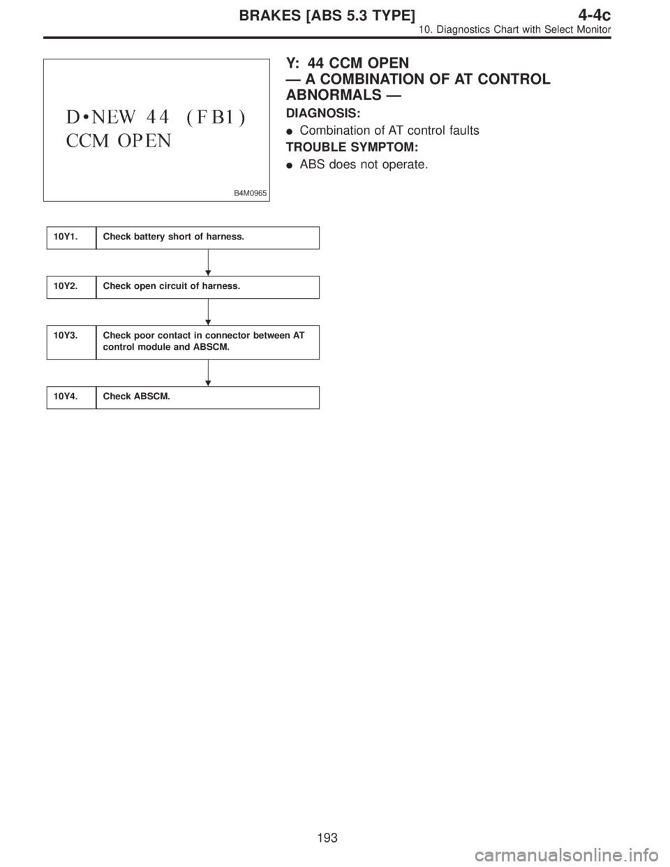
B4M0965
Y: 44 CCM OPEN
—A COMBINATION OF AT CONTROL
ABNORMALS—
DIAGNOSIS:
�Combination of AT control faults
TROUBLE SYMPTOM:
�ABS does not operate.
10Y1.Check battery short of harness.
10Y2.Check open circuit of harness.
10Y3.Check poor contact in connector between AT
control module and ABSCM.
10Y4.Check ABSCM.
�
�
�
193
4-4cBRAKES [ABS 5.3 TYPE]
10. Diagnostics Chart with Select Monitor
Page 2534 of 2890
WIRING DIAGRAM:
B4M1040
194
4-4cBRAKES [ABS 5.3 TYPE]
10. Diagnostics Chart with Select Monitor
 Start engine.
2) Idling after warm-up.
3) Measure voltage between generator B terminal and
chassis ground.
: Terminal
Generator B terminal—Chassis ground
Is voltage")
 Turn ignition switch to OFF.
2) Measure resistance between ABSCM connector and
chassis ground.
: Connector & terminal
(F49) No. 1—Chassis ground
Is re")
 Press F,0and 0on the select monitor.
2) Read the select monitor display.
: Is an ABSCM for AT model installed")
 No. 12 (+)—Chassis ground (�)
(F49) No. 39 (+)—Chassis ground")
![SUBARU LEGACY 1996 Service Repair Manual WIRING DIAGRAM:
B4M1040
194
4-4cBRAKES [ABS 5.3 TYPE]
10. Diagnostics Chart with Select Monitor](/manual-img/17/57433/w960_57433-2533.png "SUBARU LEGACY 1996 Service Repair Manual WIRING DIAGRAM:
B4M1040
194
4-4cBRAKES [ABS 5.3 TYPE]
10. Diagnostics Chart with Select Monitor")