Page 1809 of 2890
B2M0482
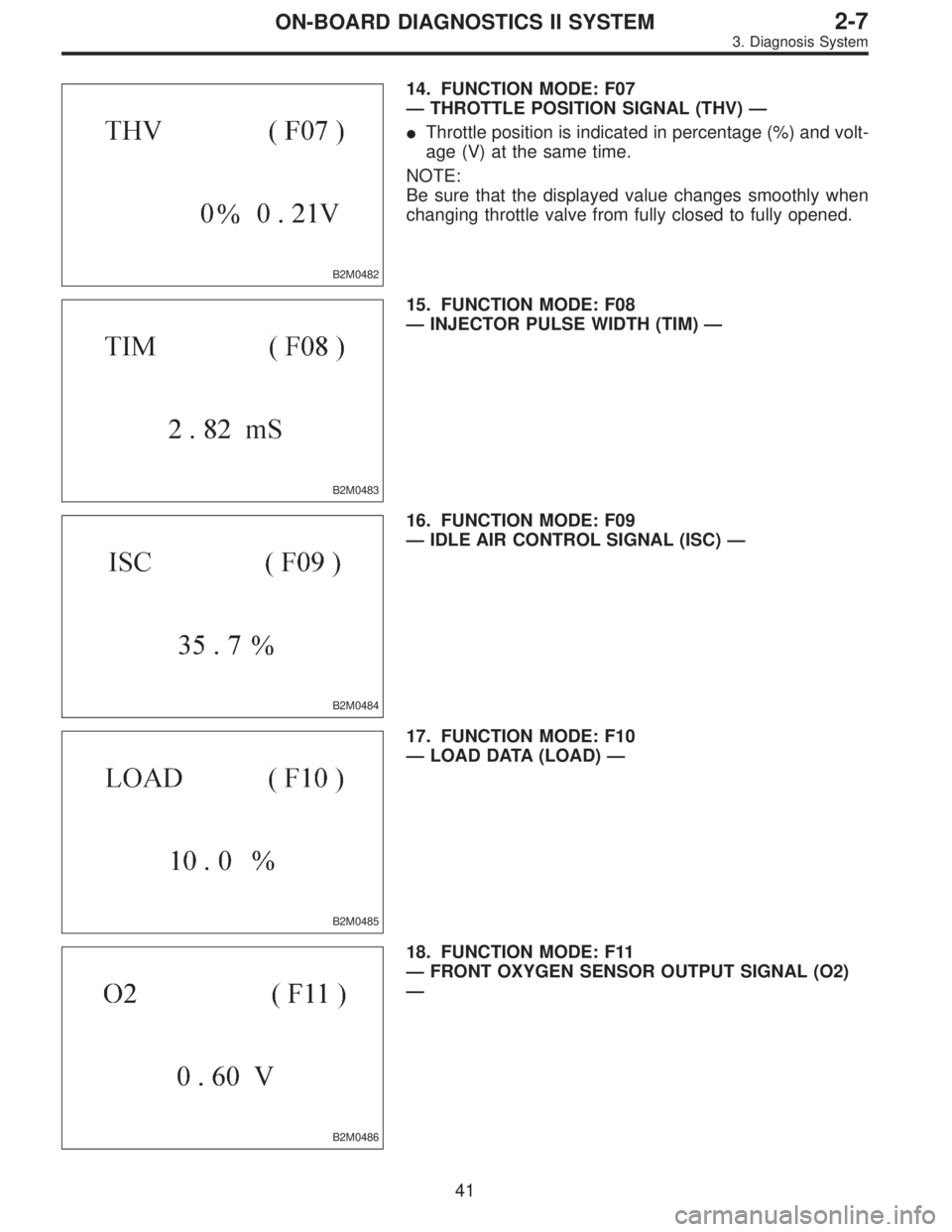
14. FUNCTION MODE: F07
—THROTTLE POSITION SIGNAL (THV)—
�Throttle position is indicated in percentage (%) and volt-
age (V) at the same time.
NOTE:
Be sure that the displayed value changes smoothly when
changing throttle valve from fully closed to fully opened.
B2M0483
15. FUNCTION MODE: F08
—INJECTOR PULSE WIDTH (TIM)—
B2M0484
16. FUNCTION MODE: F09
—IDLE AIR CONTROL SIGNAL (ISC)—
B2M0485
17. FUNCTION MODE: F10
—LOAD DATA (LOAD)—
B2M0486
18. FUNCTION MODE: F11
—FRONT OXYGEN SENSOR OUTPUT SIGNAL (O2)
—
41
2-7ON-BOARD DIAGNOSTICS II SYSTEM
3. Diagnosis System
Page 2192 of 2890
G2M0931
(4) Push the TCS OFF switch to ON. (with TCS mod-
els)
(5) Start the engine.
(6) Shift on the gear position, and keep the vehicle
speed at constant.
(7) Measure signal voltage.
Specified voltage: 2 V, or more
NOTE:
If vehicle speed increases, the width of amplitude (W)
decreases.
NOTE:
The speed difference between front and rear wheels may
light either the ABS or the ABS/TCS warning light, but this
indicates no malfunctions. When AT control diagnosis is
finished, perform the ABS or the ABS/TCS memory clear-
ance procedure of self-diagnosis system.
52
3-2AUTOMATIC TRANSMISSION AND DIFFERENTIAL
7. Diagnostic Chart with Trouble Code
Page 2721 of 2890
 Start the engine.
4) Shift on the gear position, and keep the vehicle speed
at constant.
5) Measure signal voltage.
Specified voltage (V): 2 V, or more
NOTE:
�If the vehicle speed i")
G2M0931
B6M0287
3) Start the engine.
4) Shift on the gear position, and keep the vehicle speed
at constant.
5) Measure signal voltage.
Specified voltage (V): 2 V, or more
NOTE:
�If the vehicle speed increases, the width of amplitude
(W) decreases.
�If oscilloscope is not available, check input signal
(vehicle speed signal) by using a select monitor. (Refer to
the procedure as described below.)
�Using the select monitor:
(1) Set the vehicle on free roller, or lift-up the vehicle and
support with safety stands.
(2) Turn ignition switch to OFF and set select monitor.
(3) Turn ignition switch to ON.
(4) Turn cruise control main switch to ON.
(5) Set select monitor in“F01”or“F02”mode.
(6) Drive the vehicle at speed greater than 40 km/h (25
MPH).
(7) Check that vehicle speed indication on select moni-
tor and speedometer are equal.
NOTE:
�When there is a disconnection or short circuit in the har-
ness between the meter and the cruise control module, the
indicated value will be 0 to 1.0 km/h (0 to 0.6 MPH).
�In“F01”mode, vehicle speed is indicated in mile per
hour (MPH).
In“F02”mode, vehicle speed is indicated in kilometer per
hour (km/h).
B3M0250
3. PERFORM A CIRCUIT TEST BETWEEN
COMBINATION METER AND CRUISE CONTROL
MODULE.
1) Turn ignition switch to OFF.
2) Remove combination meter.
B6M0194B
3) Disconnect connector from cruise control module.
4) Measure resistance of harness connector between
combination meter and cruise control module.
Connector & terminal / Specified resistance:
(i10) No. 10—(B94) No. 19 / 10Ω, max.
24
6-2BODY ELECTRICAL SYSTEM
8. Diagnostics Chart with Trouble Code
 Push the TCS OFF switch to ON. (with TCS mod-
els)
(5) Start the engine.
(6) Shift on the gear position, and keep the vehicle
speed at constant.
(7) Measure signal voltage.
Specified volta")