Page 964 of 2890

383505200 3.12 mm (0.1228 in)
383515200 3.15 mm (0.1240 in)
383525200 3.18 mm (0.1252 in)
383535200 3.21 mm (0.12")
Pinion height adjusting shim thicknessPart No. Thickness
383495200 3.09 mm (0.1217 in)
383505200 3.12 mm (0.1228 in)
383515200 3.15 mm (0.1240 in)
383525200 3.18 mm (0.1252 in)
383535200 3.21 mm (0.1264 in)
383545200 3.24 mm (0.1276 in)
383555200 3.27 mm (0.1287 in)
383565200 3.30 mm (0.1299 in)
383575200 3.33 mm (0.1311 in)
383585200 3.36 mm (0.1323 in)
383595200 3.39 mm (0.1335 in)
383605200 3.42 mm (0.1346 in)
383615200 3.45 mm (0.1358 in)
383625200 3.48 mm (0.1370 in)
383635200 3.51 mm (0.1382 in)
383645200 3.54 mm (0.1394 in)
383655200 3.57 mm (0.1406 in)
383665200 3.60 mm (0.1417 in)
383675200 3.63 mm (0.1429 in)
383685200 3.66 mm (0.1441 in)
Side bearing standard width—20.00 mm (0.7874 in)
Side bearing retainer shim thicknessPart No. Thickness
383475201 0.20 mm (0.0079 in)
383475202 0.25 mm (0.0098 in)
383475203 0.30 mm (0.0118 in)
383475204 0.40 mm (0.0157 in)
383475205 0.50 mm (0.0197 in)
Crown gear to drive pinion backlash
Limit0.10—0.20 mm (0.0039—0.0079 in)
Crown gear runout on its back surface 0.05 mm (0.0020 in)
Oil capacity0.8�(0.8 US qt, 0.7 Imp qt)
5
3-4SPECIFICATIONS AND SERVICE DATA
1. AWD System
Page 990 of 2890
G3M0720
9) Press-fit companion flange with ST1 and ST2.
CAUTION:
Be careful not to damage bearing.
ST1 899874100 INSTALLER
ST2 399780104 WEIGHT
G3M1052
10) Install self-locking nut. Then tighten it with ST.
ST 498427200 FLANGE WRENCH
Tightening torque:
181±15 N⋅m (18.5±1.5 kg-m, 134±11 ft-lb)
G3M0069
11) Install crown gear on differential case.
Tightening Torque:
103±10 N⋅m (10.5±1.0 kg-m, 76±7 ft-lb)
NOTE:
Tighten diagonally while tapping the bolt heads.
G3M1041
12) Before installing side bearing, measure the bearing
width by using a dial gauge, ST1 and ST2.
Standard bearing width:
20.00 mm (0.7874 in)
NOTE:
Set the dial gauge needle to zero, using a standard bear-
ing or block of specified height in advance.
ST1 398227700 WEIGHT
ST2 398237700 GAUGE
G3M0091
13) Press side bearing cone onto differential case with
ST1.
ST1 398487700 DRIFT
31
3-4SERVICE PROCEDURE
2. Rear Differential
Page 991 of 2890
 Adjusting side bearing retainer shims
(1) The drive gear backlash and side bearing preload
can be determined by the side bearing retainer shim
thickness.
(2) When replacing differ")
G3M1043
B3M0134A
14) Adjusting side bearing retainer shims
(1) The drive gear backlash and side bearing preload
can be determined by the side bearing retainer shim
thickness.
(2) When replacing differential case, differential carrier,
side bearing and side bearing retainer, obtain the right
and left retainer shim thickness from the following for-
mulas.
T
1(Left) = (A + C + G1�D) x 0.01 + 0.76�E (mm)
T
2(Right) = (B+D+G2) x 0.01 + 0.76�F (mm)
T
1&T2: Thickness of left and right side bearing
retainer shim (mm)
A & B : Number marked on differential carrier
C & D : Number marked on differential case
E & F : Difference of width of left and right side
bearing from standard width 20.0 mm,
expressed in a unit of 0.01 mm. For
example, if the bearing measured width
is 19.89 mm, value of E or F is as follows.
20.00�19.89 = 0.11 (E or F)
G
1&G2: Number marked on side bearing retainer
If a number is not marked, regard it as zero.
NOTE:
Use several shims to obtain the calculated thickness.
�Side bearing retainer shim thicknessPart No. Thickness mm (in)
383475201 0.20 (0.0079)
383475202 0.25 (0.0098)
383475203 0.30 (0.0118)
383475204 0.40 (0.0157)
383475205 0.50 (0.0197)
32
3-4SERVICE PROCEDURE
2. Rear Differential
Page 1139 of 2890
G4M0792
6) Using ST, loosen lock nut.
ST 926230000 SPANNER
G4M0793
7) Tighten adjusting screw until it no longer tightens.
G4M0794
8) Using a wrench [32 mm (1.26 in) width across flats] or
adjustable wrench, remove tie-rod.
CAUTION:
�Check ball joint for free play, and tie-rod for bends.
Replace if necessary.
�Check dust seals used with tie-rod end ball joint for
damage or deterioration. Replace if necessary.
9) Loosen adjusting screw and remove spring and sleeve.
CAUTION:
Replace spring and/or sleeve if damaged.
G4M0795
10) Disconnect pipes A and B from steering body and con-
trol valve housing.
CAUTION:
Replace pipes and/or flare nuts if damaged.
32
4-3SERVICE PROCEDURE
4. Steering Gearbox (Power Steering System) [RHD model]
Page 1193 of 2890
 or less in both directions
GOOD
�NOT GOOD
Adjust backl")
3. MEASUREMENT OF STEERING EFFORT
*4
Measure steering efforts in stand still with engine idling on
concrete road.
Result: 29.4 N (3.0 kg, 6.6 lb) or less in both directions
GOOD
�NOT GOOD
Adjust backlash.
Measure steering efforts in stand still with engine stalled on
concrete road.
Result: 294.2 N (30.0 kg, 66.2 lb) or less in both directions
NOT GOOD GOOD*4 When turning steering more
quickly than necessary from
a direction to the other direc-
tion at an engine speed over
2,000 rpm, steering effort
may be heavy. This is caused
by flow characteristic of oil
pump and is not a problem.
Adjust backlash.
Remove universal joint.
Measure steering wheel effort.
Result: Maximum force is 2.26 N (0.23 kg, 0.51 lb) or less in
both directions.
Fluctuation width is 1.08 N (0.11 kg, 0.24 lb) or less.
GOOD
�NOT GOOD
Check, readjust, replace if
necessary.
Measure folding torque of the joint.
Result: 5.49 N (0.56 kg, 1.23 lb) or less for long yoke
8.43 N (0.86 kg, 1.90 lb) or less for short yoke
GOOD
�NOT GOOD
Replace with a new one.
Check front wheels for unsteady revolution or rattling and brake
for dragging.
GOOD
�NOT GOOD
Inspect, readjust, replace if
necessary.
Remove tie-rod ends.
(To be continued.)
�
�
�
�
�
�
�
�
86
4-3DIAGNOSTICS
1. Power Steering
Page 1207 of 2890
1. Brakes
A: SPECIFICATIONS
1. MODELS WITH ABS OR ABS/TCS
Model Sedan Wagon
Engine (cc) 2200 2200
Driving system FWD AWD FWD AWD
L+ L+ LS L+ L+ OUTBACK LS
Front
brakeType Disc (Floating type, ventilated)
Effective disc diameter
mm (in)210 (8.27)
Disc thickness x Outer
diameter
mm (in)24 x 260 (0.94 x 10.24)
Effective cylinder
diameter
mm (in)57.2 (2.252)
Pad dimensions
(length x width x
thickness)
mm (in)112.4 x 44.3 x 11.0 (4.43 x 1.744 x 0.433)
Clearance adjustment Automatic adjustment
Rear
brakeType Disc (Floating type)
Effective disc diameter
mm (in)230 (9.06)
Disc thickness x Outer
diameter
mm (in)10 x 266 (0.39 x 10.47)
Effective cylinder
diameter
mm (in)34.9 (1.374) 38.1 (1.500)
Pad dimensions
(length x width x
thickness)
mm (in)92.4 x 33.7 x 10.0 (3.638 x 1.327 x 0.394)
Clearance adjustment Automatic adjustment
2
4-4SPECIFICATIONS AND SERVICE DATA
1. Brakes
Page 1208 of 2890
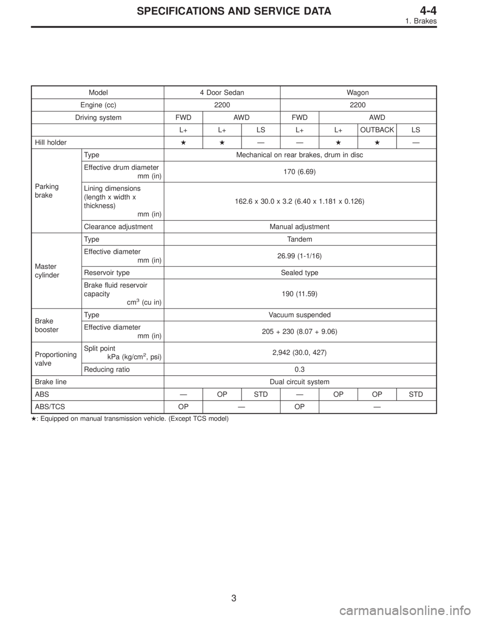
Model 4 Door Sedan Wagon
Engine (cc) 2200 2200
Driving system FWD AWD FWD AWD
L+ L+ LS L+ L+ OUTBACK LS
Hill holder��——��—
Parking
brakeType Mechanical on rear brakes, drum in disc
Effective drum diameter
mm (in)170 (6.69)
Lining dimensions
(length x width x
thickness)
mm (in)162.6 x 30.0 x 3.2 (6.40 x 1.181 x 0.126)
Clearance adjustment Manual adjustment
Master
cylinderType Tandem
Effective diameter
mm (in)26.99 (1-1/16)
Reservoir type Sealed type
Brake fluid reservoir
capacity
cm
3(cu in)190 (11.59)
Brake
boosterType Vacuum suspended
Effective diameter
mm (in)205 + 230 (8.07 + 9.06)
Proportioning
valveSplit point
kPa (kg/cm
2, psi)2,942 (30.0, 427)
Reducing ratio 0.3
Brake line Dual circuit system
ABS—OP STD—OP OP STD
ABS/TCS OP—OP—
�: Equipped on manual transmission vehicle. (Except TCS model)
3
4-4SPECIFICATIONS AND SERVICE DATA
1. Brakes
Page 1209 of 2890
2. MODELS WITHOUT ABS OR ABS/TCS
Model Sedan Wagon
Engine (cc) 2200
Driving system FWD AWD FWD AWD
L, L+ L, L+ L, L+ POST BRIGHTON L, L+ OUTBACK
Front
brakeType Disc (Floating type, ventilated)
Effective disc diameter
mm (in)210 (8.27)
Disc thickness x Outer
diameter
mm (in)24 x 260 (0.94 x 10.24)
Effective cylinder
diameter
mm (in)57.2 (2.252)
Pad dimensions
(length x width x
thickness)
mm (in)112.4 x 44.3 x 11.0 (4.43 x 1.744 x 0.433)
Clearance adjustment Automatic adjustment
Rear
brakeType Drum (Leading-Trailing type)
Effective drum diameter
mm (in)228.6 (9)
Effective cylinder
diameter
mm (in)17.4 (0.685) 19.0 (0.748)
Lining dimensions
(length x width x
thickness)
mm (in)218.8 x 35.0 x 4.1 (8.61 x 1.378 x 0.161)
Clearance adjustment Automatic adjustment
4
4-4SPECIFICATIONS AND SERVICE DATA
1. Brakes
 Press-fit companion flange with ST1 and ST2.
CAUTION:
Be careful not to damage bearing.
ST1 899874100 INSTALLER
ST2 399780104 WEIGHT
G3M1052
10) Install self-locking nut. Then tighten it wi")
![SUBARU LEGACY 1996 Service Repair Manual G4M0792
6) Using ST, loosen lock nut.
ST 926230000 SPANNER
G4M0793
7) Tighten adjusting screw until it no longer tightens.
G4M0794
8) Using a wrench [32 mm (1.26 in) width across flats] or
adjustable](/manual-img/17/57433/w960_57433-1138.png "SUBARU LEGACY 1996 Service Repair Manual G4M0792
6) Using ST, loosen lock nut.
ST 926230000 SPANNER
G4M0793
7) Tighten adjusting screw until it no longer tightens.
G4M0794
8) Using a wrench [32 mm (1.26 in) width across flats] or
adjustable")
 2200 2200
Driving system FWD AWD FWD AWD
L+ L+ LS L+ L+ OUTBACK LS
Front
brakeType Disc (Floating type, ventilat")
 2200
Driving system FWD AWD FWD AWD
L, L+ L, L+ L, L+ POST BRIGHTON L, L+ OUTBACK
Front
brakeType Disc (Floating type, ventilated)
Effect")