Page 484 of 2890
 O")
1. Engine Lubrication System
Before troubleshooting, make sure that the engine oil level
is correct and no oil leakage exists.
Trouble Possible cause Corrective action
1. Warning light remains
on.1) Oil pressure switch
failureCracked diaphragm or oil leakage within switch Replace.
Broken spring or seized contacts Replace.
2) Low oil pressureClogged oil filter Replace.
Malfunction of oil by-pass valve of oil filter Clean or replace.
Malfunction of oil relief valve of oil pump Clean or replace.
Clogged oil passage Clean.
Excessive tip clearance and side clearance of oil
pump rotor and gearReplace.
Clogged oil strainer or broken pipe Clean or replace.
3) No oil pressureInsufficient engine oil Replenish.
Broken pipe of oil strainer Replace.
Stuck oil pump rotor Replace.
2. Warning light does not
go on.1) Burn-out bulb Replace.
2) Poor contact of switch contact points Replace.
3) Disconnection of wiring Repair.
3. Warning light flickers
momentarily.1) Poor contact at terminals Repair.
2) Defective wiring harness Repair.
3) Low oil pressureCheck for the same pos-
sible causes as listed in
1.—2)
17
2-4DIAGNOSTICS
1. Engine Lubrication System
Page 529 of 2890
B2M0346
17) Disconnect connector from knock sensor.
G2M0416
18) Disconnect connector from camshaft position sensor.
G2M0408
19) Disconnect connector from crankshaft position sensor.
G2M0091
20) Disconnect connector from oil pressure switch.
G2M0296
21) Disconnect fuel hoses from pipes.
WARNING:
Catch fuel from hoses in a container.
11
2-7SERVICE PROCEDURE
4. Intake Manifold
Page 559 of 2890
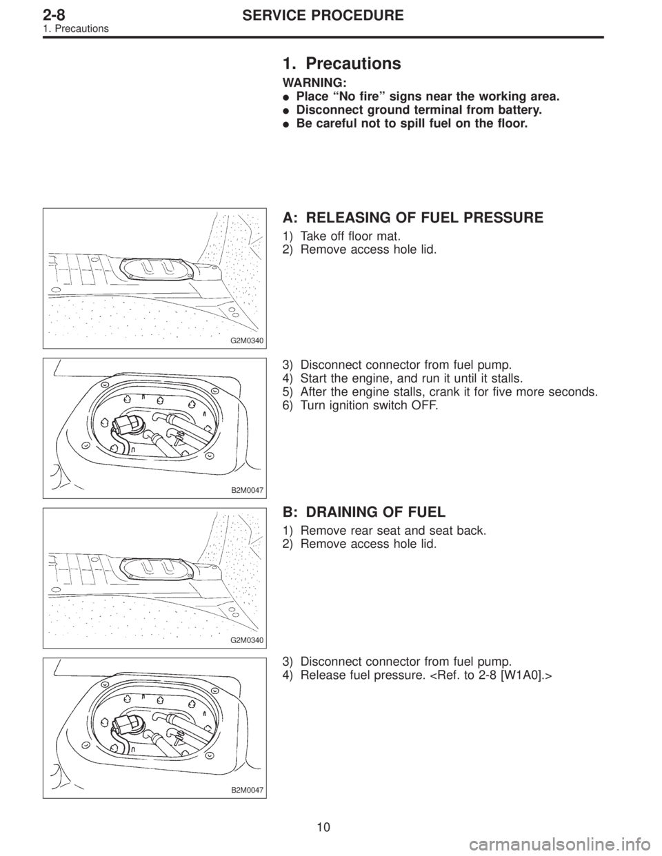
1. Precautions
WARNING:
�Place “No fire” signs near the working area.
�Disconnect ground terminal from battery.
�Be careful not to spill fuel on the floor.
G2M0340
A: RELEASING OF FUEL PRESSURE
1) Take off floor mat.
2) Remove access hole lid.
B2M0047
3) Disconnect connector from fuel pump.
4) Start the engine, and run it until it stalls.
5) After the engine stalls, crank it for five more seconds.
6) Turn ignition switch OFF.
G2M0340
B: DRAINING OF FUEL
1) Remove rear seat and seat back.
2) Remove access hole lid.
B2M0047
3) Disconnect connector from fuel pump.
4) Release fuel pressure.
10
2-8SERVICE PROCEDURE
1. Precautions
Page 560 of 2890
B2M0048A
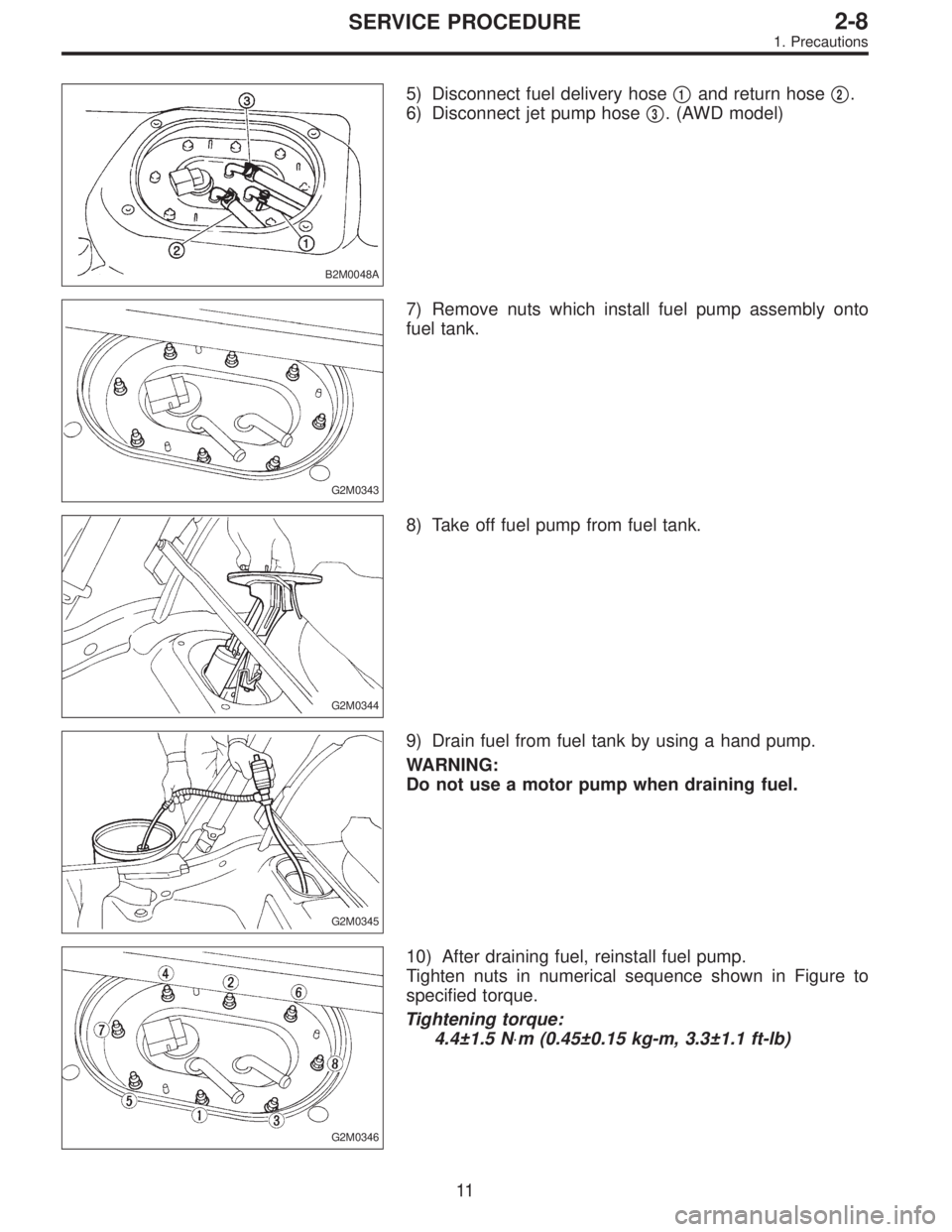
5) Disconnect fuel delivery hose�1and return hose�2.
6) Disconnect jet pump hose�
3. (AWD model)
G2M0343
7) Remove nuts which install fuel pump assembly onto
fuel tank.
G2M0344
8) Take off fuel pump from fuel tank.
G2M0345
9) Drain fuel from fuel tank by using a hand pump.
WARNING:
Do not use a motor pump when draining fuel.
G2M0346
10) After draining fuel, reinstall fuel pump.
Tighten nuts in numerical sequence shown in Figure to
specified torque.
Tightening torque:
4.4±1.5 N⋅m (0.45±0.15 kg-m, 3.3±1.1 ft-lb)
11
2-8SERVICE PROCEDURE
1. Precautions
Page 561 of 2890
B2M0049
11) On AWD model, after removing fuel sub meter unit,
drain fuel from there.
WARNING:
Do not use a motor pump when draining fuel.
2. On-Car Services
A: MEASUREMENT OF FUEL PRESSURE
1) Release fuel pressure.
2) Connect connector to fuel pump.
G2M0347
3) Disconnect fuel delivery hoses from fuel filter, and con-
nect fuel pressure gauge.
G2M0348
4) Start the engine.
5) Measure fuel pressure while disconnecting pressure
regulator vacuum hose from collector chamber.
Fuel pressure:
235 — 265 kPa (2.4 — 2.7 kg/cm
2, 34 — 38 psi)
6) After connecting pressure regulator vacuum hose, mea-
sure fuel pressure.
Fuel pressure:
177 — 206 kPa (1.8 — 2.1 kg/cm
2, 26 — 30 psi)
WARNING:
Before removing fuel pressure gauge, release fuel
pressure.
NOTE:
If out of specification as measured at step 6), check or
replace pressure regulator and pressure regulator vacuum
hose.
12
2-8SERVICE PROCEDURE
1. Precautions - 2. On-Car Services
Page 563 of 2890
G4M0545
6) Remove rear crossmember. (AWD model)
G2M0353
7) Loosen clamp, and disconnect fuel filler hose from pipe.
8) Loosen clamp, and disconnect air vent hose from air
vent pipe.
�
1Fuel filler hose
�
2Air vent hose
B2M0310A
9) Loosen clip and clamps, and disconnect fuel delivery
hose�
1, return hose�2and evaporation hose�3.
G2M0356
10) While holding fuel tank, remove bolts from bands and
dismount fuel tank.
WARNING:
A helper is required to perform step 10).
B: INSTALLATION
Installation is in the reverse order of removal. Do the fol-
lowing:
1) When installing fuel tank, have a helper hold fuel tank
while installing bands.
2) Before tightening band mounting bolts, connect fuel
system hoses.
14
2-8SERVICE PROCEDURE
3. Fuel Tank
Page 569 of 2890

G2M0366
B: INSPECTION
Connect lead harness to connector terminal of fuel pump,
and apply battery power supply to check whether the pump
operate.
WARNING:
�Wipe off the fuel completely.
�Keep battery as far apart from fuel pump as pos-
sible.
�Be sure to turn the battery supply ON and OFF on
the battery side.
�Do not run fuel pump for a long time under non-load
condition.
G2M0346
C: INSTALLATION
Installation is in the reverse order of removal. Do the fol-
lowing:
(1) Always use new gaskets.
(2) Ensure sealing portion is free from fuel or foreign
particles before installation.
(3) Tighten nuts in numerical sequence shown in Fig-
ure to specified torque.
Tightening torque:
4.4±1.5 N⋅m (0.45±0.15 kg-m, 3.3±1.1 ft-lb)
B2M0048A
7. Fuel Meter Unit
A: REMOVAL
NOTE:
Fuel meter unit is built in fuel pump assembly.
1) Release fuel pressure.
2) Disconnect fuel delivery hose�
1and return hose�2.
3) Disconnect jet pump hose�
3. (AWD model)
20
2-8SERVICE PROCEDURE
6. Fuel Pump - 7. Fuel Meter Unit
Page 631 of 2890
B2M0346
17) Disconnect connector from knock sensor.
G2M0416
18) Disconnect connector from camshaft position sensor.
G2M0408
19) Disconnect connector from crankshaft position sensor.
G2M0091
20) Disconnect connector from oil pressure switch.
G2M0296
21) Disconnect fuel hoses from pipes.
WARNING:
Catch fuel from hoses in a container.
11
2-7SERVICE PROCEDURE
4. Intake Manifold
 Disconnect connector from knock sensor.
G2M0416
18) Disconnect connector from camshaft position sensor.
G2M0408
19) Disconnect connector from crankshaft position sensor.
G2M0091
20) Discon")
 On AWD model, after removing fuel sub meter unit,
drain fuel from there.
WARNING:
Do not use a motor pump when draining fuel.
2. On-Car Services
A: MEASUREMENT OF FUEL PRESSURE
1) Release")
![SUBARU LEGACY 1996 Service Repair Manual G4M0545
6) Remove rear crossmember. (AWD model)
<Ref. to 4-1 [W11A0].>
G2M0353
7) Loosen clamp, and disconnect fuel filler hose from pipe.
8) Loosen clamp, and disconnect air vent hose from air
vent p](/manual-img/17/57433/w960_57433-562.png "SUBARU LEGACY 1996 Service Repair Manual G4M0545
6) Remove rear crossmember. (AWD model)
<Ref. to 4-1 [W11A0].>
G2M0353
7) Loosen clamp, and disconnect fuel filler hose from pipe.
8) Loosen clamp, and disconnect air vent hose from air
vent p")
 Disconnect connector from knock sensor.
G2M0416
18) Disconnect connector from camshaft position sensor.
G2M0408
19) Disconnect connector from crankshaft position sensor.
G2M0091
20) Discon")