Page 2815 of 2890
24. REAR WINDOW DEFOGGER SYSTEM
�RHD model
BUR52-01
85
6-3WIRING DIAGRAM
6. Wiring Diagram
Page 2837 of 2890
![SUBARU LEGACY 1996 Service Repair Manual 7. Electrical Unit Location
Electrical unit Refer to;
A.B.S. control module 4-4a [T300]
A.B.S. G sensor (MT) 4-4a [T300]
A/C compressor relay�
7
A/C fuse�11
A/C main fan relay 1�10
A/C main fan relay](/manual-img/17/57433/w960_57433-2836.png "SUBARU LEGACY 1996 Service Repair Manual 7. Electrical Unit Location
Electrical unit Refer to;
A.B.S. control module 4-4a [T300]
A.B.S. G sensor (MT) 4-4a [T300]
A/C compressor relay�
7
A/C fuse�11
A/C main fan relay 1�10
A/C main fan relay")
7. Electrical Unit Location
Electrical unit Refer to;
A.B.S. control module 4-4a [T300]
A.B.S. G sensor (MT) 4-4a [T300]
A/C compressor relay�
7
A/C fuse�11
A/C main fan relay 1�10
A/C main fan relay 2�8
A/C pressure switch�2
A/C sub fan relay 2�9
ATF temperature sensor 2-7 [T2B1]
Blower motor resistor�
26
Blower relay�13
Camshaft position sensor 2-7 [T2A2]
Check connector�
25
Clutch switch (MT) 6-2 [T300]
Crankshaft position sensor 2-7 [T2A2]
Cruise control module 6-2 [T300]
Cruise control pump 6-2 [T300]
Data link connector (for OBD-II G.S.T.) 2-7 [T2A1]
Data link connector (for S.S.M.) 2-7 [T2A1]
Diagnosis connector 4-4a [T300]
Diagnosis terminal (Ground) 4-4a [T300]
Door lock timer�
27
Engine control module 2-7 [T2A1]
Engine coolant temperature sensor 2-7 [T2A2]
Engine hood switch (Security) 6-2 [K6A0]
Evaporator thermoswitch�
29
F/B�15
FRESH/RECIRC actuator�28
Fuel pump relay 2-7 [T2A3]
Fuel gauge module�
31
Fuel gauge sub module (AWD)�32
FWD switch (AT)�1
Headlight alarm relay (Security) 6-2 [K6A0]
Headlight relay LH�
5
Headlight relay RH�6
Horn relay�14
Electrical unit Refer to;
Hydraulic unit (A.B.S.) 4-4a [T300]
Ignition coil 2-7 [T2A3]
Ignitor 2-7 [T2A3]
Idle air control solenoid valve 2-7 [T2A3]
Illumination control module�
21
Inhibitor switch 6-2 [T300]
Knock sensor 2-7 [T2A2]
Main fan relay�
19
Main relay 2-7 [T2A3]
Mass air flow sensor 2-7 [T2A2]
Mode actuator�
12
M/B�4
Oil pressure switch�3
Oxygen sensor 2-7 [T2A2]
Pedal stroke sensor (T.C.S.) 4-4b [T300]
Power window and sunroof relay�
24
Power window circuit breaker�23
Purge control solenoid valve 2-7 [T2A3]
Rear defogger relay�
17
Seat belt timer�20
Security control module 6-2 [K6A0]
Shift lock control module�
22
Starter interrupt relay (Security) 6-2 [K6A0]
Stop & brake switch (With cruise con-
trol)6-2 [T300]
Sunroof control module�
30
Tail and illumination relay�18
T.C.S. control module 4-4b [T300]
T.C.S. motor relay 4-4b [T300]
T.C.S. valve relay 4-4b [T300]
Throttle position sensor 2-7 [T2A2]
Test mode connector 2-7 [T2A1]
Transmission control module 2-7 [T2B1]
Turn & hazard module�
16
Vehicle speed sensor 1 2-7 [T2B1]
Vehicle speed sensor 2 2-7 [T2B1]
107
6-3WIRING DIAGRAM
7. Electrical Unit Location
Page 2839 of 2890
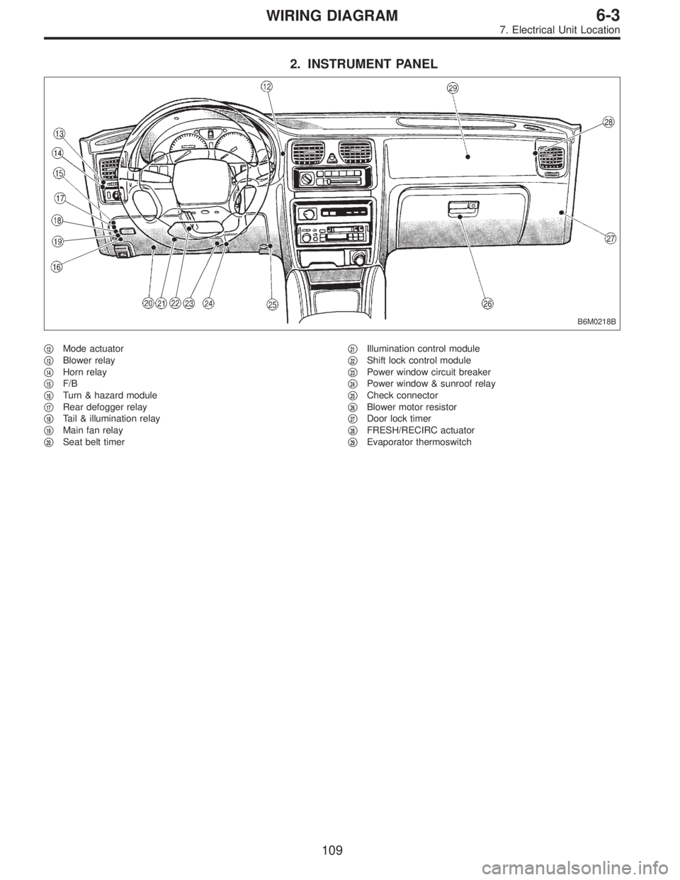
2. INSTRUMENT PANEL
B6M0218B
�12Mode actuator
�
13Blower relay
�
14Horn relay
�
15F/B
�
16Turn & hazard module
�
17Rear defogger relay
�
18Tail & illumination relay
�
19Main fan relay
�
20Seat belt timer�
21Illumination control module
�
22Shift lock control module
�
23Power window circuit breaker
�
24Power window & sunroof relay
�
25Check connector
�
26Blower motor resistor
�
27Door lock timer
�
28FRESH/RECIRC actuator
�
29Evaporator thermoswitch
109
6-3WIRING DIAGRAM
7. Electrical Unit Location
Page 2843 of 2890
8. Electrical Wiring Harness and
Ground Point
B6M0267A
�1Front wiring harness
�
2Engine wiring harness
�
3Room light cord
�
4Bulkhead wiring harness
�
5Instrument panel wiring harness
�
6Front door cord RH
�
7Rear door cord RH
�
8Rear wiring harness
�
9Trunk lid cord (Sedan)�
10Rear defogger ground cord (Sedan)
�
11Fuel tank cord
�
12Rear door cord LH
�
13Front door cord LH
�
14Sunroof cord
�
15Floor wiring harness
�
16Transmission cord
�
17Rear gate cord (Wagon)
�
18Rear oxygen sensor cord
11 3
6-3WIRING DIAGRAM
8. Electrical Wiring Harness and Ground Point
Page 2845 of 2890

12 * B-2 P1 Floor wiring harness (With ABS model)
F2 20 Blue B-2 B100 Bulkhead wiring harnes")
Connector Connecting to
No. Pole Color Area No. Name
F120 Blue B-2 P1 Floor wiring harness (With TCS model)
12 * B-2 P1 Floor wiring harness (With ABS model)
F2 20 Blue B-2 B100 Bulkhead wiring harness (With ABS model)
F3 3 Brown B-1 Front turn signal and side marker light RH
F5 1 Black B-1 Horn
F62 * C-1 Front fog light RH
2 Brown C-1 Front fog light RH (Outback with step roof)
F7 3 Black B-1 Headlight RH
F8 2 Gray B-1
Hydraulic unit (ABS)
F9 8 Gray B-1
F10 4 * B-2 TCS motor relay
F11 6 * B-2 TCS valve relay
F12 2 Black B-2 TCS pressure switch
F13 2 Black B-2 TCS motor
F14 2 Gray B-2
Hydraulic unit (TCS)
F15 12 Gray B-2
F16 3 Black C-1 Sub fan motor
F17 3 Black C-2 Radiator main fan motor
F18 2 Gray C-3 Front hood switch (Security)
F19 3 Brown C-3 Front turn signal and side marker light LH
F212 * C-2 Front fog light LH
2 Brown C-2 Front fog light LH (Outback with step roof)
F23 3 Black C-2 Headlight LH
F24 3 Gray B-2 A/C compressor
F25 1 x 2 * B-2
Generator
F26 2 Gray B-2
F27 4 Black B-3 A/C fuse (Relay holder)
F28 4 Black B-3 A/C main fan relay-1 (Relay holder)
F29 4 Black B-3 A/C sub fan relay-2 (Relay holder)
F30 4 Black B-3 A/C main fan relay-2 (Relay holder)
F31 4 Black B-3 A/C relay (Relay holder)
F32 2 Green B-2 Front washer motor
F33 2 * B-3 Rear washer motor
F34 4 Black B-3 SBF holder
F35 8 Black B-3
M/B F36 3 * B-3
F37 2 Black B-3
F38 2 Black B-3
F39 1 Brown B-3
F40 10 Gray B-4
F/B F41 3 Gray B-4
F42 5 Gray B-4
F43 3 Orange B-4 A/C diode
F44 8 * B-3 B61
Bulkhead wiring harness
F45 20 * B-3 B62
F46 2 Black B-4 B108 Bulkhead wiring harness (Outback)
F47 1 Black C-3 Horn (TAIWAN model)
F48 6 * B-3 Shield joint connector (ABS)
F49 83 Black B-3 ABS control module
F50 6 Black B-1 ABS relay box
*: Non-colored
11 5
6-3WIRING DIAGRAM
8. Electrical Wiring Harness and Ground Point
Page 2855 of 2890
 harness
B32 3 Black C-1 Turn & hazard module
B33 4 Brown B-1 Diode (Brake flui")
Connector Connecting to
No. Pole Color Area No. Name
B30 24 * C-1 D1 Front door cord LH
B31 7 Yellow C-1 AB1 SRS (Airbag) harness
B32 3 Black C-1 Turn & hazard module
B33 4 Brown B-1 Diode (Brake fluid level)
B34 3 * B-1 Diode (Door warning)
B35 2 Black B-1 Diode (Step light)
B36 22 Black C-1 i1
Instrument panel wiring
harness B37 22 * C-1 i2
B38 22 Brown C-1 i3
B39 20 Blue C-1 i4
B40 16 Gray C-2 OBD-II service connector
B41 2 * C-2 Power window circuit breaker
B42 4 * C-2Power window and sunroof
relay
B43 6 Black C-2 Illumination control module
B44 8 * C-2 Seat belt timer
B45 4 * B-1 R53 Sunroof cord
B46 4 Green B-1 Fuel pump relay
B47 6 Brown B-1 Main relay
B48 4 Blue B-1 Front fog light relay
B49 3 Black B-1 Horn relay
B50 4 * B-1 Blower relay
B51 11 Gray B-1
F/B
B52 12 Gray B-1
B53 4 * B-2 Shield joint connector (AT)
B54 12 Black B-2
Transmission control module B55 16 Black B-2
B56 20 Black B-2
B57 12 Black B-2 Shift-lock control module
B58 5 Black B-1Headlight alarm relay
(Security)
B59 5 Black B-1 Interrupt relay (Security)
B60 4 * B-2Shield joint connector (With
TCS model)
B61 8 * B-2 F44
Front wiring harness
B62 20 * B-1 F45
B63 40 Gray B-1 P10Floor harness (With TCS
model)
B64 2 Black B-2 Stop light switch
B65 4 Black B-2Stop & brake switch (With
cruise control)
B66 3 Black B-2 Pedal stroke sensor (TCS)
B67 4 Black B-2 Pedal stroke switch (TCS)
B68 5 Black B-3 Slip ring
B69 11 Black B-3
Combination switch B70 9 * B-3
B71 8 * B-3
B72 6 Black B-3 Ignition switchConnector Connecting to
No. Pole Color Area No. Name
B73 2 Black B-3 Key lock solenoid (AT)
B74 2 Black B-3 Key warning switch
B75 2 Green C-2 B76
Test mode connector
B76 2 Green C-3 B75
B77 10 Brown B-2 Mode actuator
B78 9 Yellow C-2 Data link connector
B79 14 Gray C-2 Check connector
B80 4 Blue B-2 i20Instrument panel wiring
harness
B81 1 x 2 * C-2 Diagnosis terminal (Ground)
B82 6 Black C-2 Diagnosis connector
B83 4 * C-3 Shield joint connector (E/G)
B84 96Light
blueB-3 Engine control module
B85 2 Black B-3 Diode (Lighting)
B86 4 * B-3 Blower motor resistor
B87 2 * B-3 Blower motor
B88 3 Black B-3 Evaporator thermoswitch
B89 4 Brown B-3 Diode (Security)
B90 4 * B-4 R50 Room light cord
B91 4 * B-4 FRESH/RECIRC actuator
B92 8 * B-4 Door lock timer
B93 16 Black B-4 Security control module
B94 20 Black B-4 Cruise control module
B95 2 Black B-4 Diode (Daytime running light)
B96 10 * B-4Daytime running light control
module
B97 8 * B-4 R1
Rear wiring harness B98 24 Black B-4 R2
B99 24 * B-4 R3
B100 20 Blue B-4 F2Front wiring harness (With
ABS model)
B101 24 * B-4 D11 Front door cord RH
B102 5 Black B-4 Daytime running light relay
B103 4 Blue B-4High-beam relay (Daytime
running light)
B104 4 Pink B-4 Rear power supply relay
B105 4 Blue B-1 Starter interlock relay (MT)
B106 2 * B-1 Clutch switch (MT)
B107 2 Blue B-1 Clutch switch (Cruise control)
B108 2 Black B-2 F46Front wiring harness
(Outback)
B109 4 Black C-1 Fuse holder (Outback)
B112 2 Black B-1 Diode (Front fog light)
*: Non-colored
Connector Connecting to
No. Pole Color Area No. Name
S1 3 White D-3 Cruise control sub switch
125
6-3WIRING DIAGRAM
8. Electrical Wiring Harness and Ground Point
Page 2859 of 2890

Connector Connecting to
No. Pole Color Area No. Name
i1 22 Black C-2 B36
Bulkhead wiring harness i2 22 * C-1 B37
i3 22 Brown C-1 B38
i4 20 Blue C-2 B39
i5 15 Gray C-1 F/B
i6 10 * C-1 Remote control rearview mirror switch
i7 6 Yellow B-2 Front fog light switch
i8 4 Brown B-2 Security indicator light
i9 6 * B-2 T.C.S. off switch
i10 16 Light gray B-2
Combination meter
i11 3 * B-2
i12 16 Light gray B-2 Combination meter
i13 4 * B-2 Combination meter (Airbag warning)
i14 13 * B-2 Combination meter
i15 6 * B-3 Fan switch
i16 3 * B-3 A/C switch
i17 16 * B-3 Mode control panel
i18 6 * B-3 Rear defogger switch
i19 6 Brown B-2 Cruise control main switch
i20 4 Blue B-3 B80 Bulkhead wiring harness
i21 2 Black C-3 Ash tray illumination light
i22 10 * B-3 Hazard switch
i23 2 Brown B-4 Glove box illumination light
i24 1 * C-3
Cigarette lighter
i25 3 * C-3
i26 14 * B-3 Radio
i27 2 * B-3 CD player illumination light
i28 1 Black C-3 Ground
i29 1 Black C-3 Ground (Radio)
*: Non-colored
129
6-3WIRING DIAGRAM
8. Electrical Wiring Harness and Ground Point
Page 2861 of 2890
Connector Connecting to
No. Pole Color Area No. Name
i1 22 Black C-4 B36
Bulkhead wiring harness i2 22 * C-4 B37
i3 22 Brown C-4 B38
i4 20 Blue C-4 B39
i5 15 Gray C-4 F/B
i6 10 * C-4 Remote control rearview mirror switch
i10 16 Light gray B-3
Combination meter
i11 3 * B-3
i12 16 Light gray B-3 Combination meter
i13 4 * B-3 Combination meter (Airbag warning)
i14 13 * B-3 Combination meter
i15 6 * B-2 Fan switch
i17 16 Black B-2 Mode control panel
i18 6 * B-3 Rear defogger switch
i19 6 Brown B-3 Cruise control main switch
i20 4 Blue B-2 B80 Bulkhead wiring harness
i22 10 * B-2 Hazard switch
i23 2 Brown B-2 Glove box illumination light
i24 1 * C-2
Cigarette lighter
i25 3 * C-2
i26 14 * B-2 Radio
i28 1 Black C-2 Ground
i29 1 Black C-2 Ground (Radio)
*: Non-colored
131
6-3WIRING DIAGRAM
8. Electrical Wiring Harness and Ground Point